Condensation and recovery of oil from pyrolysis gas

a technology of pyrolysis gas and condensation, which is applied in the direction of destructive distillation, gaseous mixture working up, separation process, etc., can solve the problem of unobtainable oil/water emulsion which is difficult to separate, and achieves high void fraction, prevent clogging of the nozzle, and high surface area

Inactive Publication Date: 2006-09-05
METSO MINERALS IND INC
View PDF8 Cites 55 Cited by
  • Summary
  • Abstract
  • Description
  • Claims
  • Application Information

AI Technical Summary

Benefits of technology

[0008]Hot gases from a pyrolysis process, for example a rotary kiln processing used tires, are taken to a first oil condenser. The first oil condenser comprises a packed tower with countercurrent gas / liquid flow. Various types of packing material may be used, but the preferred packing is of the Pall ring type that has high surface area and high void fraction. Cooled oil is sprayed onto the top of the packed bed and is used to cool, condense and coalesce the vapor in the incoming gas stream. By controlling the temperature and flow rate of the cooled oil and the size of the packed tower, the temperature of the gas leaving the tower can be controlled. Preferably, the temperature of the gas leaving the tower should be above the dew point of the water vapor in the gas stream. A temperature of 100° C.–105° C. is used to insure that no water is condensed in the first oil condenser. By preventing the condensation of water in the first condenser, an undesirable oil / water emulsion which is difficult to separate is not obtained.
[0009]To prevent fouling of the packing in the first oil condenser, a spray of cool oil is also directed at the underside of the packing. In this manner, the particulate matter in the incoming gas stream will adhere to the lower surface of the packing which is coated with the upwardly directed oil spray. In addition, the spray on the underside of the packing keeps the particulate matter from remaining on the packing because it is washed off as the spray from the topside of the packing passes through the packing and is collected with the oil in the sump of the first condenser. The oil collected in the sump of the first condenser is drawn from the sump through a wire mesh duplex filter. The filter collects the larger particulate matter containing the oil and removes it from the process. This prevents the particulate matter from clogging the oil spray nozzles. After the filter, a pump moves the oil through a water-cooled liquid-to-liquid heat exchanger. The cooler oil returns to the first condenser where it is used to spray onto the topside and underside of the packed bed, as previously described. A portion of the oil, equal to that condensed in the tower, is removed and is the oil product from the process. The spray nozzles used in the condenser are single fluid atomization nozzles that contain relatively large nozzle openings, i.e. 3 / 16 in. or larger, to help prevent clogging of the nozzle.
[0010]From the first oil condenser, the gases go to a second oil condenser. This second condenser operates in a similar manner to the first condenser except that the gases are cooled below the dew point of water contained in the incoming gas stream. As a result, both water and oil are collected in the sump of this condenser. However, the oil collected in the sump of the second condenser typically has a specific gravity of 0.90 to 0.95. Since the oil is significantly less dense than the water collected with it, separation of the oil and water phases may be readily accomplished. The second condenser also only requires an oil spray on the topside of the packing and does not require an oil spray directed at the underside of the packing since a large majority of the particulate matter is removed in the first stage. Again, a portion of the oil, equal to that condensed in the tower, is removed as oil product from the process.
[0011]As a result, the process of the present invention enables the recovery of greater than 95% of the oil entrained in the initial hot gas exhaust stream from the pyrolysis reactor. This oil may comprise both a high boiling pyrolysis oil (flash point of 60° C. or greater) as well as a low boiling pyrolysis oil (flash point of 34° C. or below). In addition, a gas is produced from the second condenser which is readily usable as fuel gas having minimal amounts of condensable vapors therein.

Problems solved by technology

By preventing the condensation of water in the first condenser, an undesirable oil / water emulsion which is difficult to separate is not obtained.

Method used


Image

  • Condensation and recovery of oil from pyrolysis gas
  • Condensation and recovery of oil from pyrolysis gas
  • Condensation and recovery of oil from pyrolysis gas

Examples


example 1

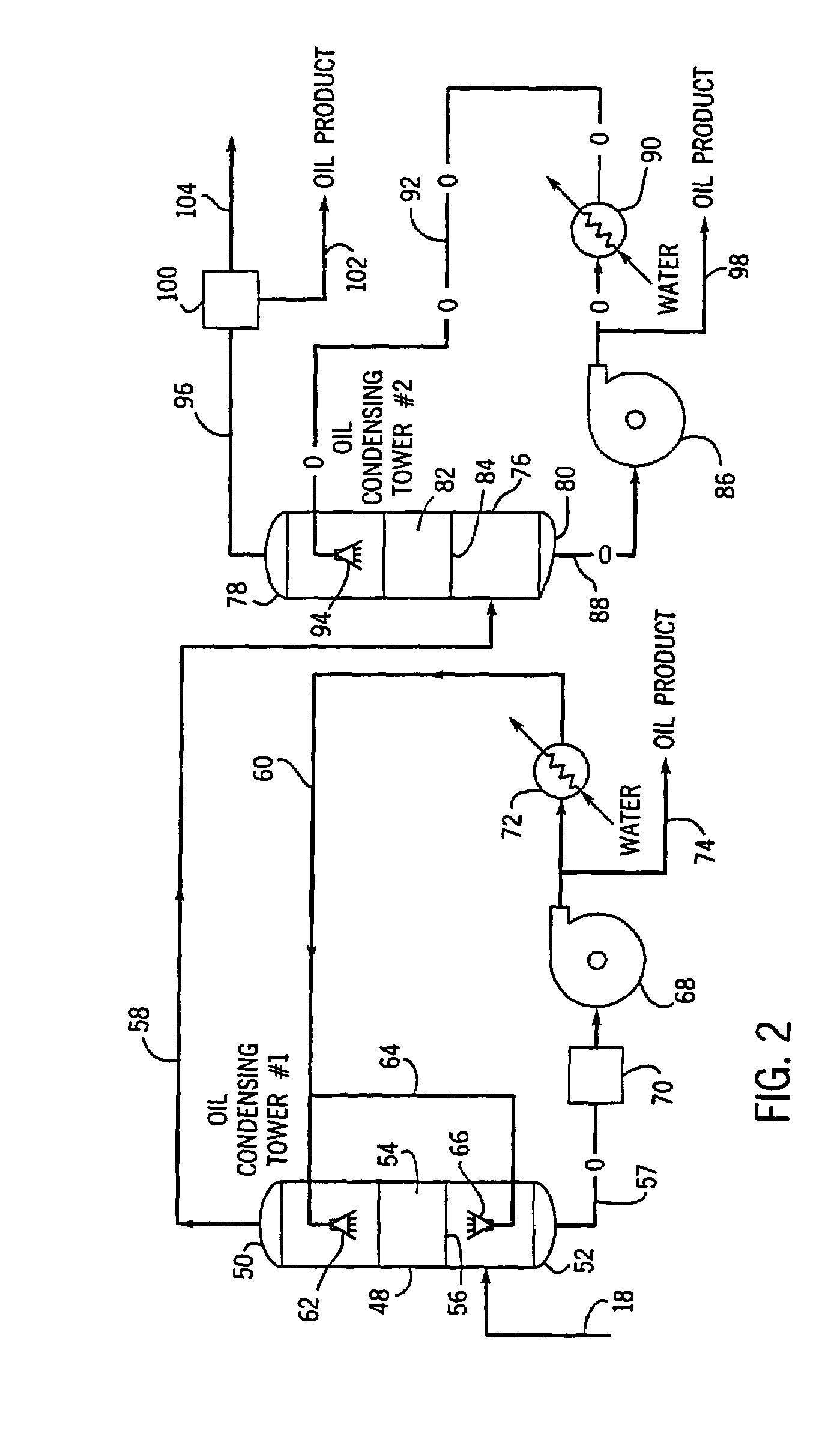
[0032]The following is sample data that may be used to size a 100 ton per day tire pyrolysis plant built in accordance with FIG. 2.

[0033]

Tower 48Diameter = 30 inchesHeight = 26 feetFeed inlet line 18Gas temp. = 850° F.Sump outlet line 57Oil temp. = 150° F.Heat exchanger 72 cooling waterWater temp. = 85° F.Flow rate = 300 gpmOil recycle line 60Oil temp. = 90° F.Flow rate = 175 gpmTower outlet line 58Gas temp. = 212° F.Tower 76Diameter = 24 inchesHeight = 10 feetSump outlet line 88Oil temp. = 100° F.Heat exchanger 90 cooling waterWater temp. = 85° F.Flow rate = 70 gpmOil recycle line 92Oil temp. = 90° F.Flow rate = 85 gpmTower outlet line 96Gas temp. = 100° F.

example 2

[0034]The following is a chart showing the composition of oil collected in a pilot plant study from a system constructed as illustrated in FIG. 2 for two different sources of tires, i.e. Source 1 was from used automobile tires, and Source 2 was from reject or off-spec OEM automobile tires.

[0035]

Distri-ViscosityPourConradsonPentanebution(Centis-PointCarbonInsolublesSpecificCarbonHydrogenSulfurAsh(Wt. %)tokes)(° F.)(Wt. %)(Wt. %)Gravity(Wt. %)(Wt. %)(Wt. %)(Wt. %)Source 1 (used Auto Tires)Primary83.5%6.27−227.90.970.9987.858.671.180.04Secondary2.6%0.95Demister13.8%0.893−221.20.070.8786.319.480.850.01Source 2 (Off-spec OEM Auto Tires)Primary85.2%13.10−2211.25.11.0387.818.181.320.09Secondary4.0%0.97Demister10.8%0.952−221.90.70.8987.379.320.490.01

example 3

[0036]The following is a chart showing a typical non-condensable gas analysis for the product obtained from line 104 in a tire pyrolysis pilot plant constructed as illustrated in FIG. 2.

[0037]


PUM

PropertyMeasurementUnit
Fractionaaaaaaaaaa
Flash pointaaaaaaaaaa

Abstract

A system and process for the recovery of oil from the pyrolysis of material containing hydrocarbons such as shredded vehicle tires. The system utilizes a pair of sequentially positioned packed towers to recover at least 95% of the oil contained in the pyrolysis gases. The first packed tower operates above the dew point of the water vapor in the pyrolysis gases to insure that no water is condensed and obtain a primary oil fraction having oil with a high flash point of about 60° C. or greater and a primary vapor fraction containing additional oils, fuel gases and water vapor. The primary vapor fraction is fed to the second packed tower which operates below the dew point of the water vapor to condense the water and oil having a low flash point of 34° C. or below, and provide a secondary vapor fraction containing valuable fuel gases.

Description

CROSS-REFERENCE TO RELATED APPLICATIONS[0001]This application is the U.S. national stage application of International Application PCT / US00 / 11627, filed Apr. 28, 2000, which international application was published on Nov. 16, 2000 as International Publication WO 00 / 68338 in the English language. The International Application claims priority of U.S. Provisional Patent Application 60 / 132,634, filed May 5, 1999.BACKGROUND OF THE INVENTION[0002]The present invention relates generally to the recovery of usable products from the pyrolysis of material containing hydrocarbons. More specifically, the present invention relates to the recovery of oil from the gas formed when scrap tires are pyrolysed.[0003]As the supply of available landfill space decreases, environmentally sensitive disposal of consumed vehicle tires presents an ever increasing problem. In the United States alone, over 280,000,000 vehicle tires are scrapped and shipped to landfills each year. Although some of the used vehicle ...

Claims


Application Information

Patent Timeline
IPC IPC(8): B01D5/00
CPCB01D5/0036B01D5/0057C10G70/043C10G1/002C10G1/10C10B53/07Y02P20/143
Inventor WEINECKE, MICHAEL H.UNTERWEGER, ROBERT J.
Owner METSO MINERALS IND INC
Why Eureka
Try Eureka