
Non-contact high-voltage electrometer architecture with low-voltage feedback

a low-voltage feedback, non-contact technology, applied in the field of voltmeters, can solve the problems inconvenient measurement, and inability to fully decouple the gap variation from the measurement accuracy, so as to reduce the cost of electrometers, maintain the accuracy of existing high-end commercial instruments, and solve the problem of inconvenient in-line trim

Active Publication Date: 2006-08-29
ANALOG DEVICES INC
View PDF9 Cites 48 Cited by
  • Summary
  • Abstract
  • Description
  • Claims
  • Application Information

AI Technical Summary

Benefits of technology

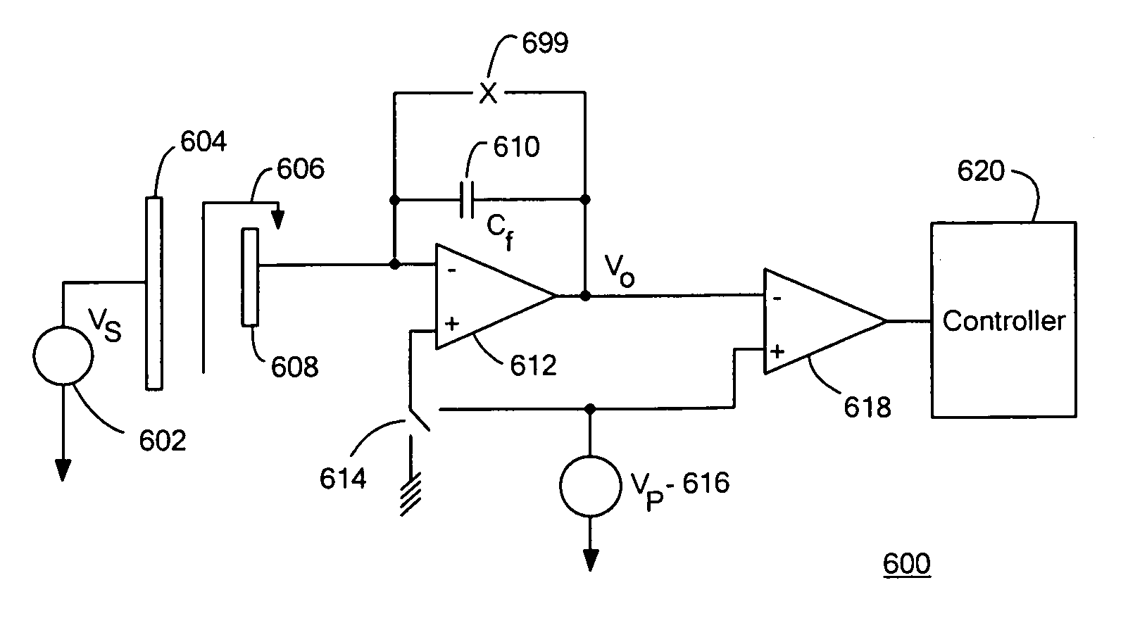
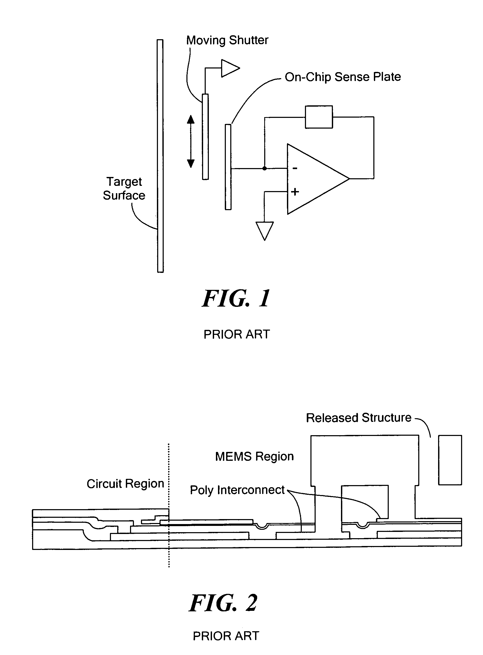
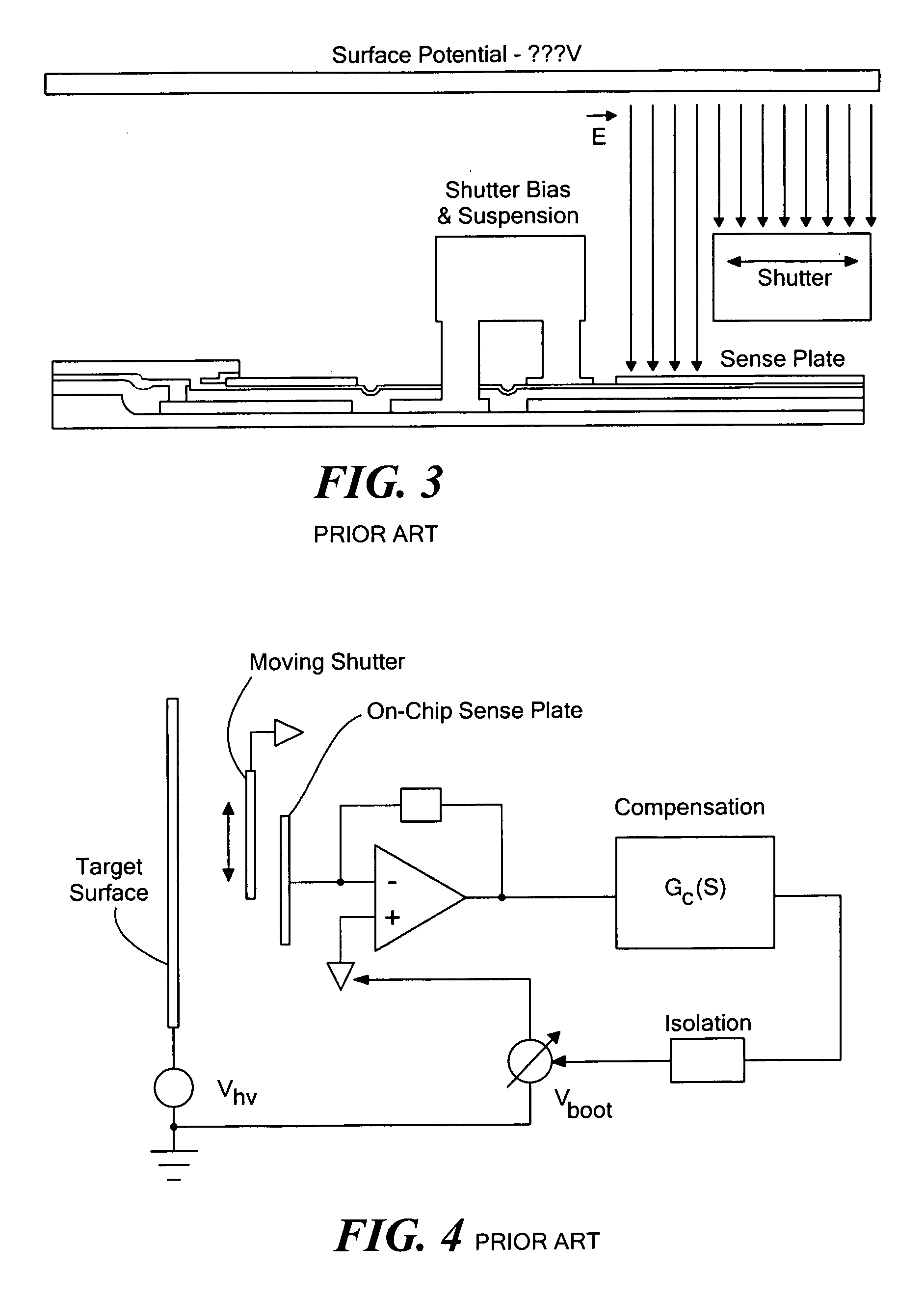
[0008]Various embodiments of the invention relate to a non-contact voltmeter that measures high-voltage potentials on a target surface with a combination of low-voltage circuitry and MEMS devices. Non-contact metrology has many applications, but is particularly important to the field of xerography and laser printing, where non-contact voltmeters allow for precision measurement and control of the imaging drum's potential. One significant issue associated with existing non-contact voltmeter architectures is the sensitivity of the measurement to variations in the sensor-to-target surface spacing, which makes in-line trim difficult. The spacing sensitivity can be addressed, however, by employing a servo loop. Existing servo architectures, however, require either hybrid high-voltage circuitry that is expensive and bulky, or the use of fairly complicated “ac feedback” techniques that do not fully decouple the gap variation from the measurement accuracy. The architecture described herein allows for full decoupling of the gap and environmental variations while employing only low-voltage devices. When implemented in an integrated MEMS process technology, for example, this architecture allows for significant reduction in electrometer cost while maintaining the accuracy of existing high-end commercial instruments.

Problems solved by technology

One significant issue associated with existing non-contact voltmeter architectures is the sensitivity of the measurement to variations in the sensor-to-target surface spacing, which makes in-line trim difficult.
Existing servo architectures, however, require either hybrid high-voltage circuitry that is expensive and bulky, or the use of fairly complicated “ac feedback” techniques that do not fully decouple the gap variation from the measurement accuracy.

Method used


Image

  • Non-contact high-voltage electrometer architecture with low-voltage feedback
  • Non-contact high-voltage electrometer architecture with low-voltage feedback
  • Non-contact high-voltage electrometer architecture with low-voltage feedback

Examples


Embodiment Construction

[0028]Shortcomings of existing non-contact voltmeter designs can be addressed with either of two improved servo architectures. The first architecture overcomes the shortcomings of a lateral field-mill's Co to Cm ratio by multi-sampling the detector capacitance during the sampling step. The second architecture fully eliminates the gap sensitivity by using a parallel reference capacitance Co that is significantly larger than the modulation capacitor. Both techniques improve on the state-of-the-art, allow for ease of MEMS integration, and allow use of only low-voltage electronics.

Improved Non-Contact Voltmeter Architecture #1: Multi-Sampling

[0029]In an exemplary multi-sampling architecture, a movable shutter is used to selectively expose a detector plate with an equivalent capacitance Cm to a target surface having an unknown voltage potential Vs. In one sample stage, a charge Vs*B is measured, where B is proportional to Cm. In another sample stage, a charge Vp*B is measured, where Vp i...


PUM


Abstract

A voltmeter measures an unknown voltage on a target surface using multiple sampling stages or a parallel reference capacitor. A movable shutter may alternately be closed during resetting of a voltage measuring circuit and opened so as to expose a detector plate to the target surface during two sampling stages. Alternatively, the shutter may be used to modulate exposure of a detector plate to the target surface.

Description

PRIORITY[0001]This application claims priority from U.S. Provisional Patent Application No. 60 / 555,233 entitled Non-contact, High-voltage Electrometer Architecture with Low-voltage Feedback, filed on Mar. 22, 2004 in the name of Timothy J. Denison, which is hereby incorporated herein by reference in its entirety.FIELD OF THE INVENTION[0002]The invention generally relates to voltmeters, and, more particularly, to non-contact voltmeters that measure a voltage on a target surface without touching the target surface.BACKGROUND OF THE INVENTION[0003]Non-contact measurement of a target surface's potential relies on the detection of an electric field. As discussed in D. P. Loconto, High-sensitivity Micromechanical Electrostatic Voltmeter, M. S. Thesis, UC Berkeley EECS, 1992 and R. D. Houston, Non-contacting ESV Technology, Xerox Corporation Internal Report, Rochester, N.Y., March 1983, both of which are hereby incorporated herein by reference in their entireties, the measurement of electr...

Claims


Application Information

Patent Timeline
IPC IPC(8): G01R31/02G01R27/26G01R29/12
CPCG01R29/12
Inventor DENISON, TIMOTHY J.
Owner ANALOG DEVICES INC
Learn More