
Carburetor for internal combustion engine

a technology for internal combustion engines and carburetors, which is applied in the direction of machines/engines, combustible gas purification/modification, and separation processes, etc., can solve the problems of deteriorating the output and fuel consumption exhaust gas emission, and insufficient facilitation of atomization, so as to improve the output and fuel consumption and exhaust gas emission of the internal combustion engine. , the effect of simple structur

Inactive Publication Date: 2006-08-15
GOTO SHINJI
View PDF18 Cites 15 Cited by
  • Summary
  • Abstract
  • Description
  • Claims
  • Application Information

AI Technical Summary

Benefits of technology

This design enhances fuel atomization, resulting in improved engine output, reduced fuel consumption, and better exhaust gas emission by ensuring uniform air-fuel mixing, while maintaining a simple and cost-effective structure.

Problems solved by technology

Then, the fuel 7 discharged from the nozzle 3 becomes hard to be atomized, thereby possibly deteriorating an output and a fuel consumption of the internal combustion engine as well as an exhaust gas emission.
However, this system cannot facilitate atomization sufficiently.
However, according to the above system, new and expensive parts need be added for better atomization of the fuel so as to improve the output and the fuel consumption of the internal combustion engine as well as the exhaust gas emission.
Moreover, the structure becomes complicated.
Thus, it has disadvantages in terms of costs.
However, such improvements could not be adopted in the carburetor that is generally cheaper than the fuel injection device.
As described above, it has been difficult to improve atomization of the fuel with a simple structure and improve maximum output and fuel consumption as well as exhaust gas emission in the internal combustion engine.
However, the aforementioned carburetor 1 cannot atomize the fuel sufficiently or needs additionally the expensive parts to improve the atomization.
Thus, there has been a problem that, if the air accelerated by the throttle valve 4 deviates from the leading end position of the fuel discharge nozzle 3, the fuel is hard to be atomized.

Method used


Image

  • Carburetor for internal combustion engine
  • Carburetor for internal combustion engine
  • Carburetor for internal combustion engine

Examples


first embodiment

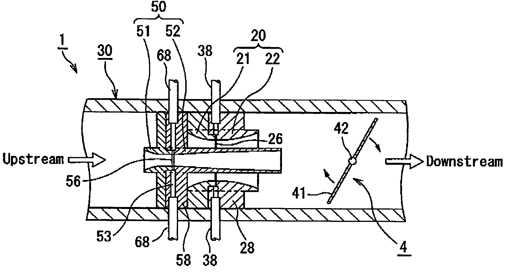
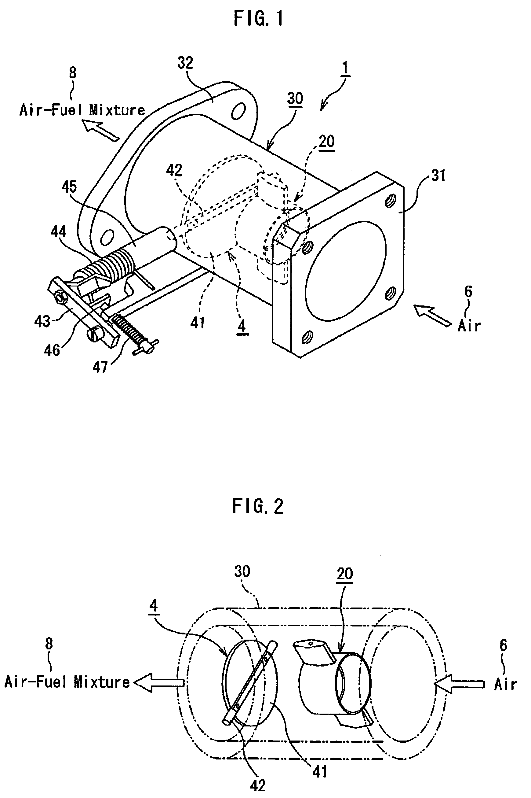
[0089]FIG. 1 is a perspective view of an overall structure of a carburetor for an internal combustion engine including an annular venturi tube and a throttle valve according to a first embodiment of the invention. FIG. 2 is a perspective view of a positional relationship between the annular venturi tube and the throttle valve of FIG. 1. FIG. 3 is a perspective view of the annular venturi tube of FIG. 2. FIG. 4 is a cross-sectional view taken along the line B—B of FIG. 3. FIG. 5 is a cross-sectional view taken along the line C—C of FIG. 4. FIG. 6 is a cross-sectional view taken along the line D—D of FIG. 3. FIG. 7 is a view showing an example of a specific cross-section of a main part of a fuel discharge portion of the annular venturi tube of FIG. 3. FIG. 8 is a view showing modified example of a specific cross-section of a main part of a fuel discharge portion of the annular venturi tube of FIG. 3. FIG. 9 is a cross-sectional view showing an assembled state of the annular venturi tu...

second embodiment

[0113]FIG. 12 is a cross-sectional view of an annular venturi tube of a carburetor for an internal combustion engine according to a second embodiment of the invention. FIG. 13 is a cross-sectional view showing a modified example of an annular venturi tube of a carburetor for an internal combustion engine according to the second embodiment of the invention.

[0114]Referring to FIG. 12, a plurality of fuel discharging small holes or pores 27 is formed on the veturi tube 20 for atomizing the fuel. That is, in the second embodiment, four fuel discharging pores 27 are formed along a circumference of the inner wall surface of the annular venturi tube 20 in place of the fine annular slit of the fuel discharging portion 26. In case of providing the four fuel discharging pores 27 in the second embodiment, a first pair of fuel discharging pores 27 is formed at such points as to be at right angles to the valve shaft 42 of the throttle valve 4 in a plane parallel to the valve shaft 42. Moreover, ...

third embodiment

[0119]FIG. 14 is a perspective view showing an overall structure of an annular venturi tube of a carburetor for an internal combustion engine according to a third embodiment of the invention. FIG. 15 is a perspective view cut along an imaginary centerline of FIG. 14 and showing a partial structure thereof FIG. 16 is an enlarged partial cross-section of FIG. 15.

[0120]Referring to FIG. 14 to FIG. 16, the third embodiment of an annular venturi tube 20 has a fuel discharging portion 26A of a fine annular slit that opens toward an inner peripheral side. The fuel discharging portion 26A is connected to the fuel routes 26a of square cross-section via plural small holes or pores 26B. That is, the liquid fuel supplied to the fuel route 26a via the fuel supplying route 23 passes through the pores 26B so as to be fed to the fuel discharging portion 26A that is the annular slit.

[0121]In the third embodiment of the carburetor for the internal combustion engine, the fuel discharging portion 26A f...


PUM

PropertyMeasurementUnit
angleaaaaaaaaaa
angleaaaaaaaaaa
angleaaaaaaaaaa

Abstract

A carburetor for an internal combustion engine has an intake pipe having a throttle valve plate therein. An annular venturi tube is disposed upstream or downstream of the throttle valve plate inside the intake pipe. The annular venturi tube is located at a predetermined interval with the throttle valve plate. The annular venturi tube has a fine continuous annular slit or four or more annularly arranged fuel discharging pores so as to atomize the fuel thereat. Atomization is always carried out near a position where a fastest air moves so as to improve the atomization and a uniform air-fuel mixture, thereby improving an output, fuel consumption and exhaust gas emission of the internal combustion engine.

Description

BACKGROUND OF THE INVENTION[0001]1. Field of the Invention[0002]This invention relates to a carburetor for an internal combustion engine that generates air-fuel mixture for the internal combustion engine, and is particularly applicable to the internal combustion engine for an automobile, a motorcycle, a scooter, a snowmobile, a personal watercraft, etc.[0003]2. Description of the Related Art[0004]FIG. 42 shows structure of main parts of conventional carburetors for internal combustion engines. FIG. 42 is an explanatory drawing showing a structure in which a venturi portion is disposed upstream of a throttle valve.[0005]In FIG. 42, a carburetor 1 of an internal combustion engine has a venturi portion 2. The venturi portion 2 is structured so as to squeeze an air breathed in the carburetor 1 and to increase a speed of the air. A fuel 5 of a liquid state is supplied to the carburetor 1. A fuel discharge nozzle 3 vaporizes the fuel 5 while the air 6 is breathed in the carburetor 1 so th...

Claims


Application Information

Patent Timeline
Patent Type & Authority Patents(United States)
IPC IPC(8): F02M19/10F02M19/08
CPCF02M19/08F02M19/10Y10S261/55Y10S261/12
Inventor GOTO, SHINJI
Owner GOTO SHINJI
Learn More