
Controlled local/global and micro/macro-porous 3D plastic, polymer and ceramic/cement composite scaffold fabrication and applications thereof

a technology of micro-macro-porous and micro-porous plastics, applied in the direction of 3d object support structures, program control, foundry moulds, etc., can solve the problems of difficult fabrication, difficult to precisely control the pore geometry and interconnectivity, and difficult to meet the mechanical properties of hard tissue repair, etc., to improve the control of global pore orientation, size and geometry, and the effect of reducing drug screening costs

Inactive Publication Date: 2006-08-08
RGT UNIV OF MICHIGAN
View PDF13 Cites 106 Cited by
  • Summary
  • Abstract
  • Description
  • Claims
  • Application Information

AI Technical Summary

Benefits of technology

[0016]In accordance with the foregoing, the present invention provides three dimensional structures with designed and controlled local-porous and global-porous internal architectures. Enhanced control of global-pore orientation, branching, interconnectivity, size, and geometry is provided compared to current SFF techniques. Additionally, a larger variety of local-pore architectures are possible. The disclosed methods allow for fabrication of structures from more materials than currently possible with existing SFF fabrication and for post fabrication surface modification of these materials. Moreover, methods to fabricate mechanically robust porous composite structures containing a number of plastics or combinations of plastics and ceramic (and / or cements) are provided. These methods provide for 3D structure fabrication from more material blends and combinations of discrete material regions than currently available. Additionally, the mechanical strength of structures fabricated using these methods both in the build direction and at the composite material interface regions is improved. Novel designs and constructs created from these structures are presented for use as tissue regeneration scaffolds, bioreactor culture substrates, perfusion (advection) assisted diffusion exchangers, 3D templates for screening material / cell interaction with identical architectures, and living tissue constructs for screening the effects of pathogens and drugs derived from proteomic data and pharmacology science on human tissues in vitro. The disclosed methods enable the fabrication of engineered tissues that are mechanically and biologically functional. Constructs fabricated with this technology constitute a large reduction in drug screening costs and an advancement in “lab on chip”, biosensor, and cell manufactured drug technologies.

Problems solved by technology

However, the mechanical property requirements for hard tissue repair are difficult to satisfy using polymer / ceramic blend composites in which the ceramic and polymer components are mixed and occupy the same space.
This is because large amounts of ceramic must be incorporated, making fabrication difficult.
Although several manufacturing techniques exist to create scaffolds, precise control of pore geometry and interconnectivity is difficult.
Such random connections may not provide optimal scaffold permeability for tissue ingrowth nor optimal connectivity to maximize regenerated tissue mechanical properties.
Unfortunately, the number of materials that can be used for each direct SFF manufacturing method is limited by the manufacturing process.
Additionally, the incorporation of local pores in a direct SFF fabricated global pored scaffold is difficult.
Current direct SFF manufacturing is limited to manufacturing global pores with widths greater than 100 μm because of inherent limitations on the minimum size feature.
However, a versatile method to manufacture biomimetic structures in the microscopic range, for example structures that mimic human trabecular bone or 3D vascular branching, has not been available.
However, current 3D local-pore scaffold fabrication methods do not allow fabrication of pores with designed geometry, orientation, branching, interconnectivity, and size.
Global-pore manufacturing methods, including current SFF fabrication techniques, are not suitable for varied micro-pore structure fabrication and provide limited incorporation of local-pores within a global-porous structure.

Method used


Image

  • Controlled local/global and micro/macro-porous 3D plastic, polymer and ceramic/cement composite scaffold fabrication and applications thereof
  • Controlled local/global and micro/macro-porous 3D plastic, polymer and ceramic/cement composite scaffold fabrication and applications thereof
  • Controlled local/global and micro/macro-porous 3D plastic, polymer and ceramic/cement composite scaffold fabrication and applications thereof

Examples


Embodiment Construction

[0042]The following description of the preferred embodiments is merely exemplary in nature and is in no way intended to limit the invention, its application, or uses.

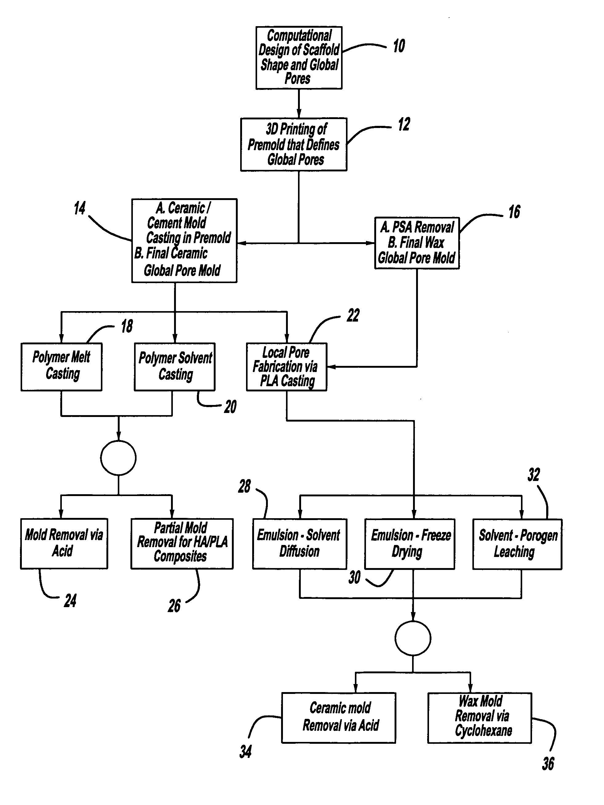
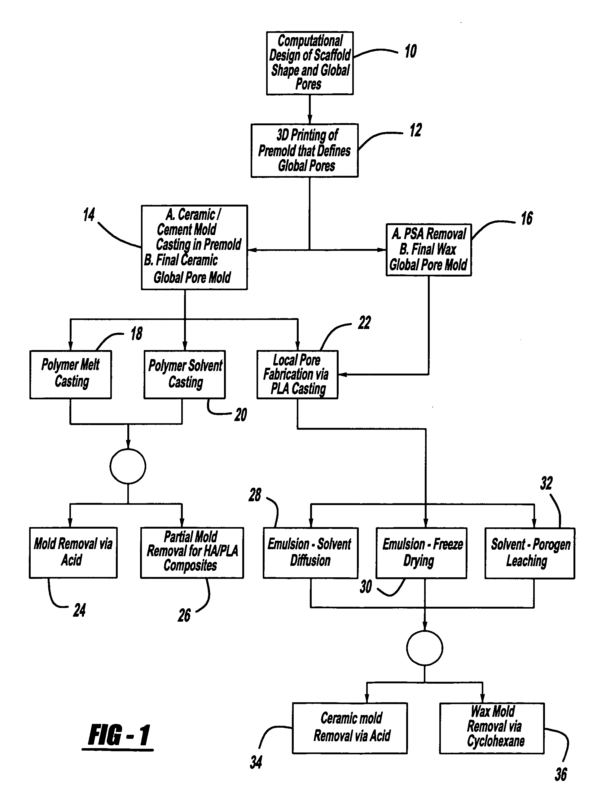
[0043]To circumvent the limitations of the prior art and combine the benefits of local pore manufacturing and direct SFF fabrication, an indirect SFF scaffold manufacturing technique is provided. More particularly, the present invention provides a set of molds, casting methods, mold removal, and structure post fabrication modification techniques that are compatible with image-based design (IBD) methods and with solvent, melt, and slurry casting of polymers and ceramics.

[0044]The indirect SFF fabrication method of the present invention combines image based design with SFF fabrication to precisely control scaffold architecture and material composition. This method provides simultaneous control of scaffold external shape to match implant site geometry, internal architecture to yield biomimetic structures, and global pore s...


PUM

PropertyMeasurementUnit
particle sizeaaaaaaaaaa
diameteraaaaaaaaaa
diameteraaaaaaaaaa

Abstract

An indirect solid free form scaffold manufacturing technique is provided. More particularly, the present invention provides a set of molds, casting methods, mold removals, and surface modification techniques that are compatible with image-based design methods and with solvent, melt, and slurry casting of polymers and ceramics.

Description

CROSS-REFERENCE TO RELATED APPLICATIONS[0001]This application claims the benefit of U.S. Provisional Application No. 60 / 300,353, filed Jun. 22, 2001 now abandoned.FIELD OF THE INVENTION[0002]The present invention relates to methods for producing three dimensional structures with designed and controlled micro-porous and macro-porous locally and globally pored internal architectures using solid free form fabrication techniques.BACKGROUND OF THE INVENTION[0003]Tissue reconstruction, regeneration of damaged tissues and organs, artificial organ production, and fabrication of living tissue constructs for proteomic, drug interaction, drug delivery, and pathogen analyses often requires the fabrication of tissue templates (scaffolds). Control over structure porosity in such scaffolds is critical. Precise control of scaffold porosity and internal pore architecture parameters (e.g. pore geometry, size, interconnectivity, orientation, and branching) is necessary to maximize nutrient diffusion, ...

Claims


Application Information

Patent Timeline
Patent Type & Authority Patents(United States)
IPC IPC(8): B29C33/38B29C39/02B29C44/02A61F2/00A61F2/06A61F2/08A61F2/28A61F2/30B22C9/00B29C33/52B29C43/00B29C67/00C04B35/447G05B19/4099
CPCA61F2/30756A61F2/30942B22C9/00B29C33/3835B29C33/3842B29C33/52B29C39/021B29C67/0081B29C67/0092C04B35/447C04B35/6264C04B35/63C04B35/632C04B35/634G05B19/4099A61F2/062G05B2219/45204A61F2/0811A61F2/28A61F2002/0086A61F2002/0894A61F2002/30199A61F2002/30678A61F2002/30766A61F2002/3092A61F2002/3093A61F2002/30948A61F2002/30952A61F2002/30957A61F2230/0063A61F2240/002A61F2240/004A61F2310/00293B29C43/006B29C2791/001B29K2105/04B29K2995/0094B29L2031/7532A61F2/08B29C64/165B29C64/40B33Y80/00B33Y70/00A61F2002/30677
Inventor TABOAS, JUANMADDOX, RACHEL DKREBSBACH, PAUL HHOLLISTER, SCOTT JCHU, TIEN-MIN GABRIEL
Owner RGT UNIV OF MICHIGAN
Learn More