
Method for gasifying organic materials and mixtures of materials

Inactive Publication Date: 2006-07-18
ELFGEN HERTA MRS +3
View PDF13 Cites 24 Cited by
  • Summary
  • Abstract
  • Description
  • Claims
  • Application Information

AI Technical Summary

Benefits of technology

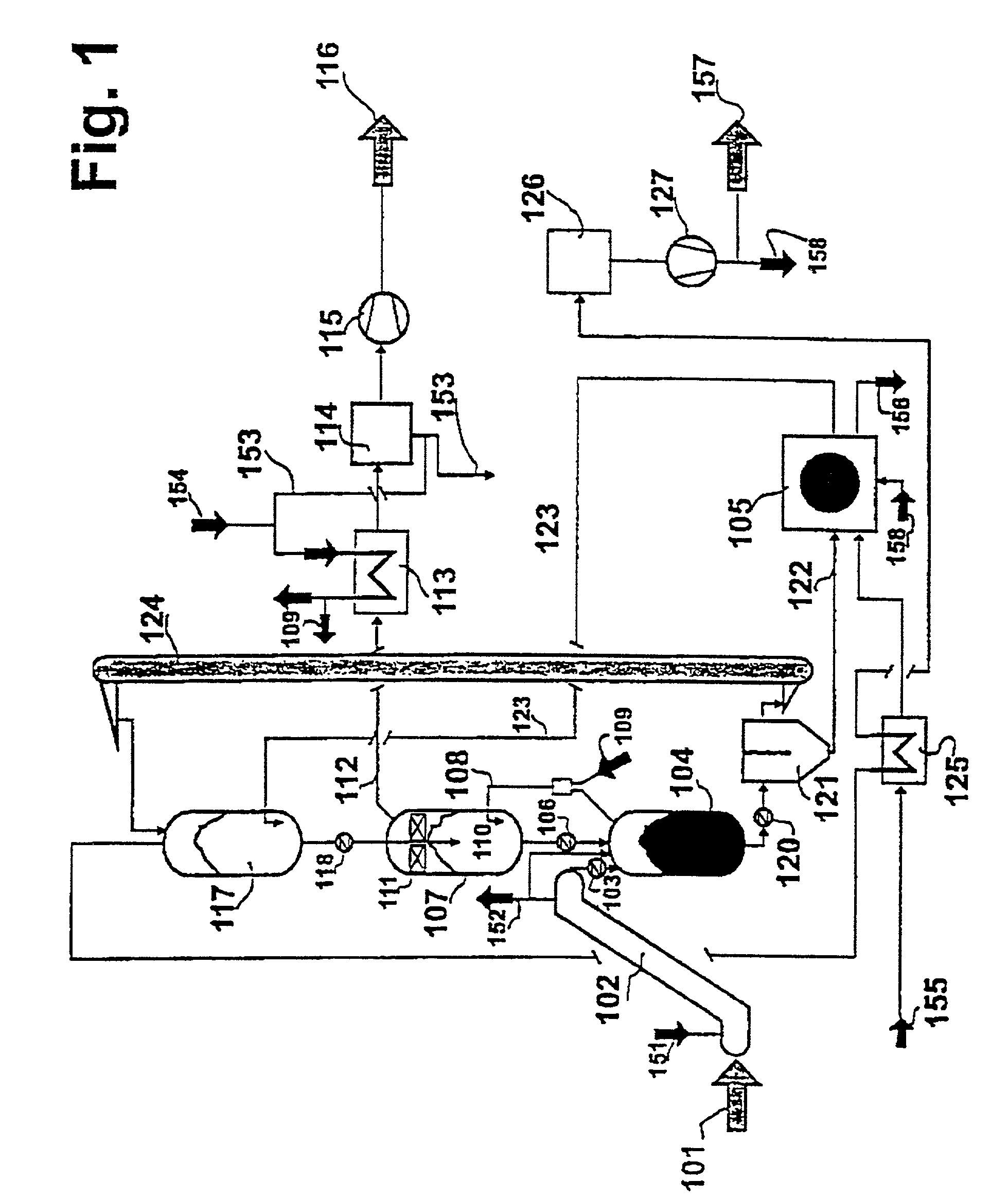
[0012]The invention is based on the problem of providing a method that can be carried in a simple way for producing a high-quality and undiluted product gas with a high calorific value; with low expenditure for the equipment; and in which, furthermore, the use of fluidized beds or heat exchangers having high temperatures on both sides is avoided, and in which the heat is transferred from the firing stage into the heat-carrying medium in a particularly defined manner.
[0015]According to the invention, the pyrolysis of the organic substance is carried out in a reactor that permits converting the heat required for the heating up, and the drying steps and the pyrolysis to be carried out in a manner as effectively as possible, in conjunction with the greatest possible simplicity in terms of equipment requirements, and a robust mode of operation. Consequently a migrating bed-type reactor or a rotating drum are considered for this task, as a rule. The pyrolysis temperature will then preferably be in a range of from 500° to 650° C.
[0020]According to the invention, the method of the invention opens up at least two basic possibilities for controlling the circulation of the heat-carrying medium. With respect to the heat-carrying medium, it is possible to successively connect the second reaction zone and the pyrolysis reactor one after the other, in series or in parallel. The important advantage offered by the series connection lies in the simplicity of the equipment: the heating-up zone, the second reaction zone and the pyrolysis reactor are interconnected among each other, so that the heat-carrying medium is moving through this arrangement, driven by force of gravity from the top downwards. Versus the arrangement described in (2), the pyrolysis stage has been changed to the extent that the pyrolysis no longer needs to be carried out with a very much greater amount of heat-carrying medium having, however, a distinctly lower temperature. If, for example, the heat-carrying medium enters the second reaction zone for the reforming purpose with a temperature of around 1050° C., it will exit from said zone while still having temperature of only about 750° C. With the parallel connection, the pyrolysis stage is not changed vis-à-vis the arrangement described in (2). However, a higher expenditure in terms of equipment has to be expected due to the fact the hot stream of heat-carrying medium has been divided, allocating it to the pyrolysis reactor and the second reaction zone, and is subsequently united again. The parallel connection, therefore, has to be given preference in cases in which it is advantageous if the charged material comes into contact with particularly hot heat-carrying medium.
[0021]Finally, the addition of process steam to the pyrolysis gases prior to the reforming step is carried out in the second reaction zone. This is addressed in the following as well. The process steam has to be admixed in an excess amount with respect to the homogeneous reactions occurring in the gas phase that have to be expected to occur, because any possible formation of carbon black can be consequently suppressed only in this way. A basis for this consists in maintaining a defined steam concentration in the fresh product gas, specifically amounting to, for example 20% by volume or more. On the other hand, it has to be expected that controlling the addition of process steam quantitatively with a steam concentration serving as the measuring quantity will require a great deal of expenditure and will be costly. It is deemed to be better to adjust a fixed value that is controlled via a measurement of the quantity depending on the capacity, which possibly may be carried out in any case. One possibility for realizing the method as defined by the invention that needs to be mentioned in any case lies in the selection of the site where the process steam is mixed with the pyrolysis gas. This mixing process has to take place prior to the entry of the mixture into the second reaction zone of the reformer at the latest; however, said site may be shifted upstream to the pyrolysis reactor, and there to any desired location within the pyrolysis reactor situated up to its lower end. The lower end of the pyrolysis reactor is meant in this connection to be the site from where the mixture comprising the heat-carrying medium and the solid, carbon-containing residue exits. This does change the division of the heat realized between the pyrolysis and the reforming stages; however, flushing of the pyrolysis with steam, which is added within the vicinity of the site where the solids exit from the pyrolysis reactor, offers advantages in the last analysis under a number of aspects: firstly, the temperature of the pyrolysis gas is not lowered in this way at any point on its way to the second reaction zone, so no condensation has to be expected to occur. Secondly, it is known from (3) that it is possible to increase the yield of volatile components in the pyrolysis of biomasses by rinsing with steam. This can be advantageous because an excessively high yield of solid pyrolysis product beyond the heat requirement of the method will reduce the yield of product gas and in connection therewith the degree of efficiency of the cold gas. Thirdly and finally, this constitutes a preventive measure for avoiding possible leakage of pyrolysis gas in the direction of the separation stage, where the heat-carrying medium and the pyrolysis gas are separated.

Problems solved by technology

However, a substantial expansion of the idea is represented by the fact that the heat of the firing stage is transferred into the heat-carrying medium in a defined and forcible manner, because if the pyrolysis coke and the heat-carrying medium are admitted into the firing stage in the form of a mixture, as it has been described in (2), it has to be expected that de-mixing of the heat-carrying medium and the pyrolysis coke will occur, for example on a combustion grate, so that the heat-carrying medium will not only be heated up inadequately in the course of the combustion process, but will even be cooled by the current of combustion air streaming in through the grate.
However, in conjunction with the present method, a rotating tubular furnace would represent a very costly firing system with poor admixture of the air, while a fluidized bed is disregarded for the reasons stated above.

Method used


Image

  • Method for gasifying organic materials and mixtures of materials
  • Method for gasifying organic materials and mixtures of materials

Examples


Embodiment Construction

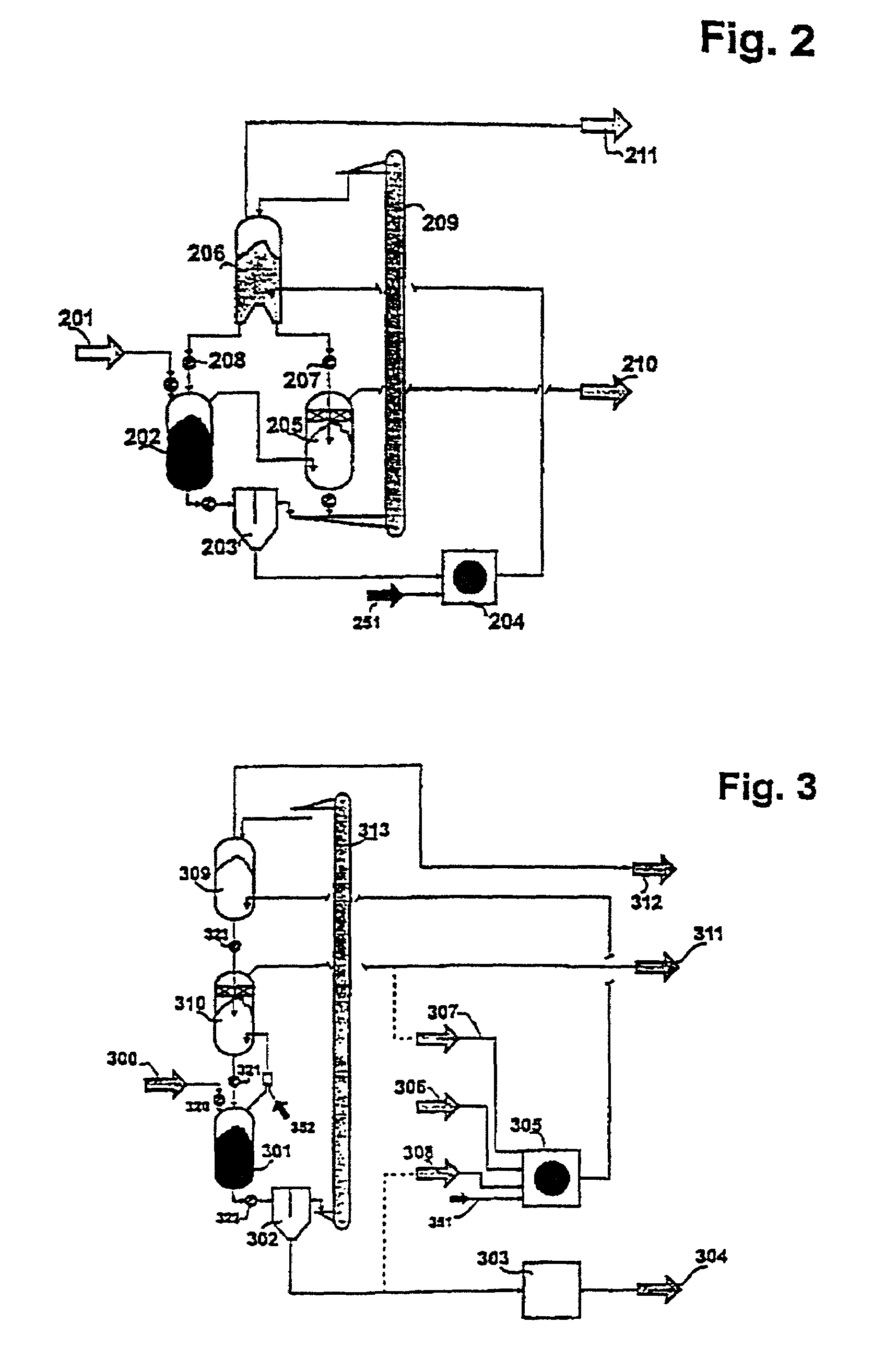
[0025]FIG. 1 shows a possible embodiment of the object of the invention. This embodiment relates to the arrangement of the series connection described in the foregoing, in which the heating-up zone, the second reaction zone (the reformer) and the pyrolysis reactor are successively connected one after the other from the top down. The charged material 101 is supplied to the pyrolysis reactor 104 via a conveyor system 102 and the gate 103. The conveyor system 102 is a conveyor screw, a belt conveyor or a similar system that may be heated, whereby the low-temperature heat 151 obtained by exploiting the off-heat of the exhaust gas and the product gas (see farther below) can be advantageously used specifically for raising the overall degree of efficiency. If an open system is used, the vapors 152 are exhausted into the environment, or otherwise added either to the pyrolysis reactor 104 or the firing stage 105. Adding the vapors to the pyrolysis reactor 104 has the advantage that a lesser ...


PUM


Abstract

The aim of the invention is to provide a method for gasifying organic materials which is simple to carry out and requires minimal equipment and which produced an undiluted gas of high calorific value. The inventive method should eliminate the need to use fluid beds and heat exchangers with high temperatures on both sides, with the heat being transferred from the furnace to a heat-carrying medium in a particularly defined way. To this end, the feed material is divided into a volatile phase and a solid carbon-containing residue in the pyrolysis reactor by circulating a hot heat-carrying medium. After the reaction agent has been added, said volatile phase is converted into the product gas by further heating in the reaction area, also using the heat-carrying medium. The solid, carbon-containing residue is separated from the heat-carrying medium in the separating stage and burnt in the furnace. The heat-carrying medium is heated by the waste gases of the furnace in the heating area and then returned to the reformer and then the pyrolysis reactor.

Description

CROSS REFERENCE TO RELATED APPLICATIONS[0001]Applicants claim priority under 35 U.S.C. §119 of German Application No. 199 45 771.9 filed Sep. 24, 1999. Applicants also claim priority under 35 U.S.C. 365 of PCT / EP00 / 09275 filed Sep. 22, 2000. The international application under PCT article 21(2) was not published in English.BACKGROUND OF THE INVENTION[0002]1. Field of the Invention[0003]The invention relates to a method for gasifying organic materials and mixtures of materials as defined in the invention.[0004]2. The Prior Art[0005]A process for gasifying organic substances and mixtures of substances is known from U.S. Pat. No. 4,568,362 (1), in which the organic substances are admitted into a pyrolysis reactor, in which these substances come into contact with a heat-carrying medium. Such contact leads to a high rate of pyrolysis and the substances are converted into pyrolysis products, i.e. pyrolysis gases containing condensable substances and solid, carbon-containing substances. Th...

Claims


Application Information

Patent Timeline
IPC IPC(8): C01B3/24C10B49/16F23G5/027C10B49/18C10B53/02C10J1/207C10J3/00C10J3/02C10J3/46F23G5/14
CPCC10B49/16C10B49/18C10B53/02C10J3/66C10K3/02Y02E50/14C10J2200/158C10J2200/06C10J2300/1884C10J2300/1892C10J2200/15Y02P20/129Y02E50/10
Inventor MUHLEN, HEINZ-JURGENSCHMID, CHRISTOPH
Owner ELFGEN HERTA MRS
Learn More