
Method and apparatus for grinding a continuously casting product

a technology of continuous casting and product, which is applied in the direction of grinding machines, work treatment devices, instruments, etc., can solve the problems of high maintenance expenditure, severe caking of grinding chips on the apparatus, and high cost of additional installation of auxiliary aggregates, so as to achieve efficient and fast as well as precise manner

Inactive Publication Date: 2014-04-29
SMS LOGISTIKSYST
View PDF21 Cites 2 Cited by
  • Summary
  • Abstract
  • Description
  • Claims
  • Application Information

AI Technical Summary

Benefits of technology

The invention provides a method and apparatus for machining continuous cast workpiece with high manufacturing quality, while eliminating high expenditures associated with prior art grinders. The grinding tool can be efficiently and fast, while the method and apparatus should remove grinding chips effectively. The apparatus includes a protective hood for the grinding tool, that can be rotated and pivoted to change grinding tools. This eliminates the need for a separate grinder (auxiliary aggregate) and allows for efficient and precise grinding of both wide and narrow faces without compromising quality.

Problems solved by technology

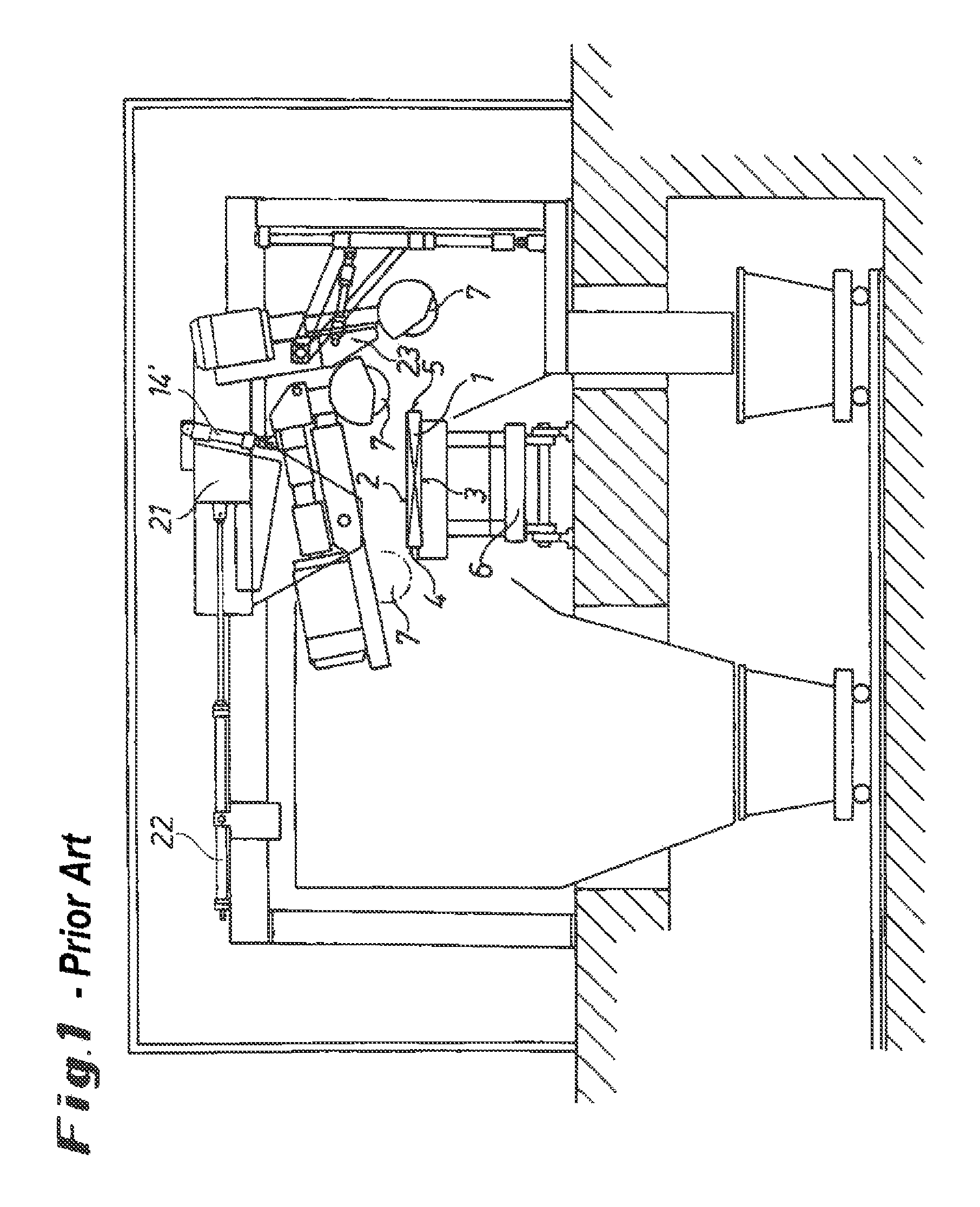
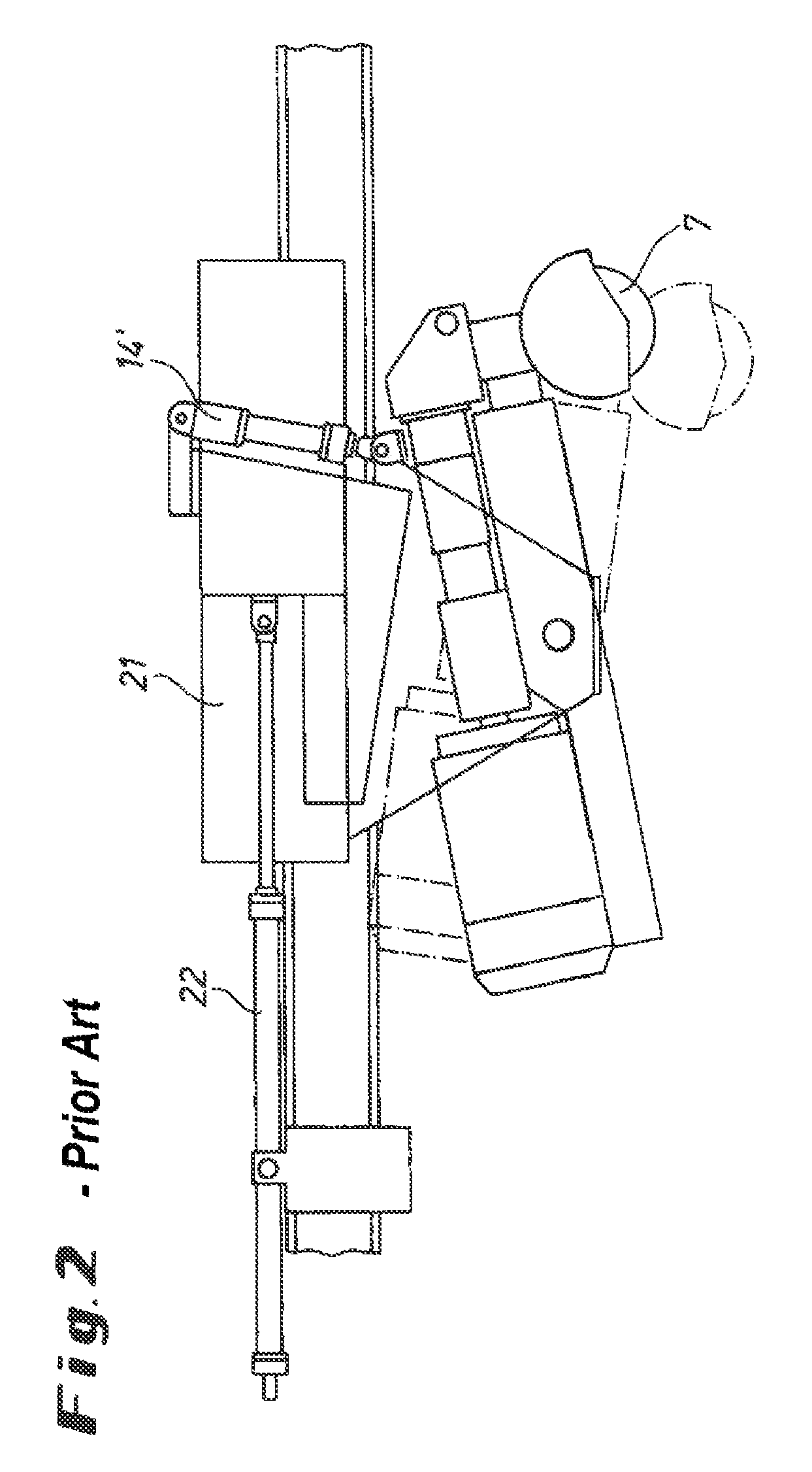
The expenditures associated with the additional installation of an auxiliary aggregate are relatively high.
Moreover, one problem is that severe caking of grinding chips on the apparatus can occur if the path of flying chips cannot be optimized.
Thus, in case of the known solutions, high maintenance expenditures are required.

Method used


Image

  • Method and apparatus for grinding a continuously casting product
  • Method and apparatus for grinding a continuously casting product
  • Method and apparatus for grinding a continuously casting product

Examples


Embodiment Construction

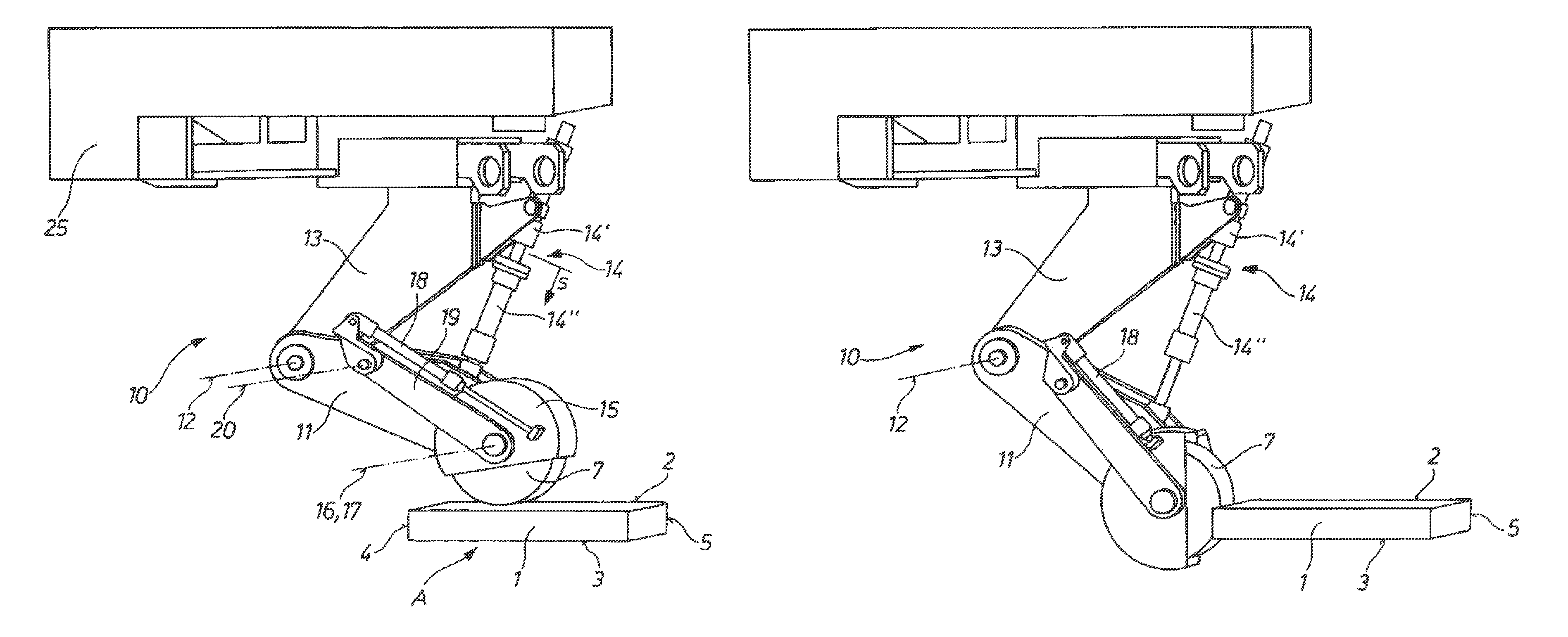
[0035]FIG. 4 schematically illustrates an apparatus for grinding a slab 1 that works according to the invention. The slab is of rectangular cross-section as shown in FIG. 4; the slab 1 extends with its longitudinal axis in a direction perpendicular to the drawing plane. Accordingly, the slab 1 has two wide faces 2 and 3 (broad sides) and two narrow faces 4 and 5 (narrow sides).

[0036]The slab 1 rests with its lower wide face 3 on a grinding table 6. This working position of the slab 1 is designated by A. During the method according to the invention, the slab 1 remains in this working position A. After the method is carried out, the slab is turned by 180° about its longitudinal axis and the method is repeated.

[0037]The slab surface is machined here by grinding in order to be able to make a finished product with sufficient quality from the slab. To this end, a grinder is provided of which only the grinding wheel 7 is shown in FIG. 4. Arrow 8 indicates the rotational direction of the gr...


PUM

PropertyMeasurementUnit
actuating forceaaaaaaaaaa
circumferenceaaaaaaaaaa
rotationaaaaaaaaaa

Abstract

The invention relates to a method for grinding a continuous casting product (1), in particular a slab, wherein the continuous casting product (1) in the cross-section has a rectangular contour comprising two long sides (2, 3) disposed opposite of each other and two short sides (4, 5) disposed opposite of each other, wherein in a working position (A), in which the continuous casting product (1) rests on a grinding table (6) with one of the long sides (2) thereof, one of the long sides (2) of the continuous casting product (1) is subjected to a surface treatment by means of at least one grinding tool (7). In order to achieve a higher quality in a simple and fast manner when working the continuous casting product and to be able to collect the grinding chips in a simple manner in the process, after or before grinding the long side (2) of the continuous casting product (1) in the working position (A), according to the invention at least one of the short sides (4, 5) is subjected to a surface treatment using the at least one grinding tool (7). The invention further relates to a device for grinding a continuous casting product (1).

Description

CROSS REFERENCE TO RELATED APPLICATIONS[0001]This application is the US-national stage of PCT application PCT / EP2010 / 001729, filed 19 Mar. 2010, published 23 Sep. 2010 as WO2010 / 105838, and claiming the priority of German patent application 102009013481.6 itself filed 19 Mar. 2009.FIELD OF THE INVENTION[0002]The invention relates to a method of grinding a continuously cast workpiece, in particular a slab, where the continuously cast workpiece is of rectangular cross section and has two wide faces disposed opposite each other and two narrow faces disposed opposite each other, and in a working position in which the continuously cast workpiece rests with one of its wide faces on a grinding table one of the wide faces of the continuously cast workpiece is surface treated by at least one grinding tool. The invention further relates to an apparatus for grinding a continuously cast workpiece.BACKGROUND OF THE INVENTION[0003]Continuously cast workpieces, in particular slabs, are mostly subj...

Claims


Application Information

Patent Timeline
Patent Type & Authority Patents(United States)
IPC IPC(8): B24B1/00
CPCB24B7/005B22D11/12B24B27/04B21B45/04
Inventor SCHILLER, GUENTER
Owner SMS LOGISTIKSYST
Learn More