
Multi-channel digital/analog converter arrangement

a converter arrangement and digital/analog technology, applied in the direction of electronic switching, pulse technique, instruments, etc., can solve the problems of processing and processing data on different data, and achieve the effects of increasing data rate, high data rate, and high expenditur

Active Publication Date: 2008-09-23
INFINEON TECH AG
View PDF17 Cites 1 Cited by
  • Summary
  • Abstract
  • Description
  • Claims
  • Application Information

AI Technical Summary

Benefits of technology

The present invention provides a multi-channel digital / analog converter arrangement for converting a number of digital input signals into an analog output signal. The arrangement includes a digital multiplexer which combines the digital input signals by means of a single digital high-speed multiplexer. The tuning device in the arrangement separates the data channels from each other as much as possible to minimize processing steps and the associated risks of processing devices. The combined data signals are then directly coupled into the downstream digital / analog converter. The invention reduces the risk of data loss and provides a high data rate with low latency. The invention also includes a synchronization device for aligning the data signals and a controllable output switching device for clock-synchronous reading of the data input signals. The invention is interference-proof and allows for selective adjustment of the logic levels of the output signal.

Problems solved by technology

A further finding consists in that, by comparison, the treatment and processing of the data on different data paths, instead, is uncritical since there the data are present at a significantly reduced data rate and / or volume of data depending on how many data paths there are and what quantity of data are to be processed, which generally makes lower demands on the corresponding processing devices.

Method used


Image

  • Multi-channel digital/analog converter arrangement
  • Multi-channel digital/analog converter arrangement
  • Multi-channel digital/analog converter arrangement

Examples


Embodiment Construction

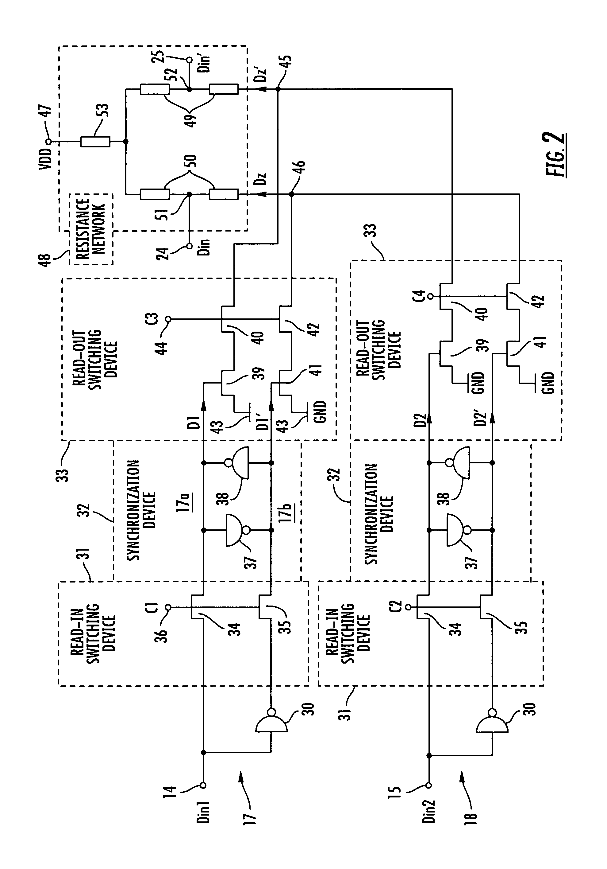
[0023]In all figures of the drawing, identical and functionally identical elements, features and signals have been provided with the same reference symbols unless otherwise specified.

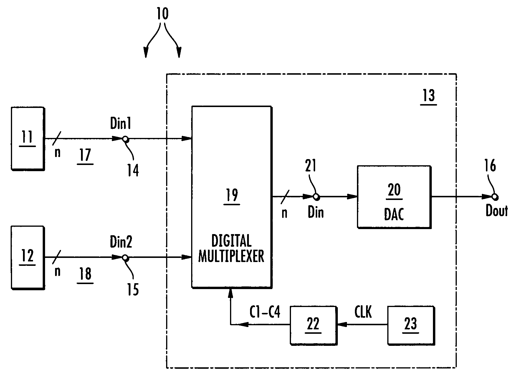
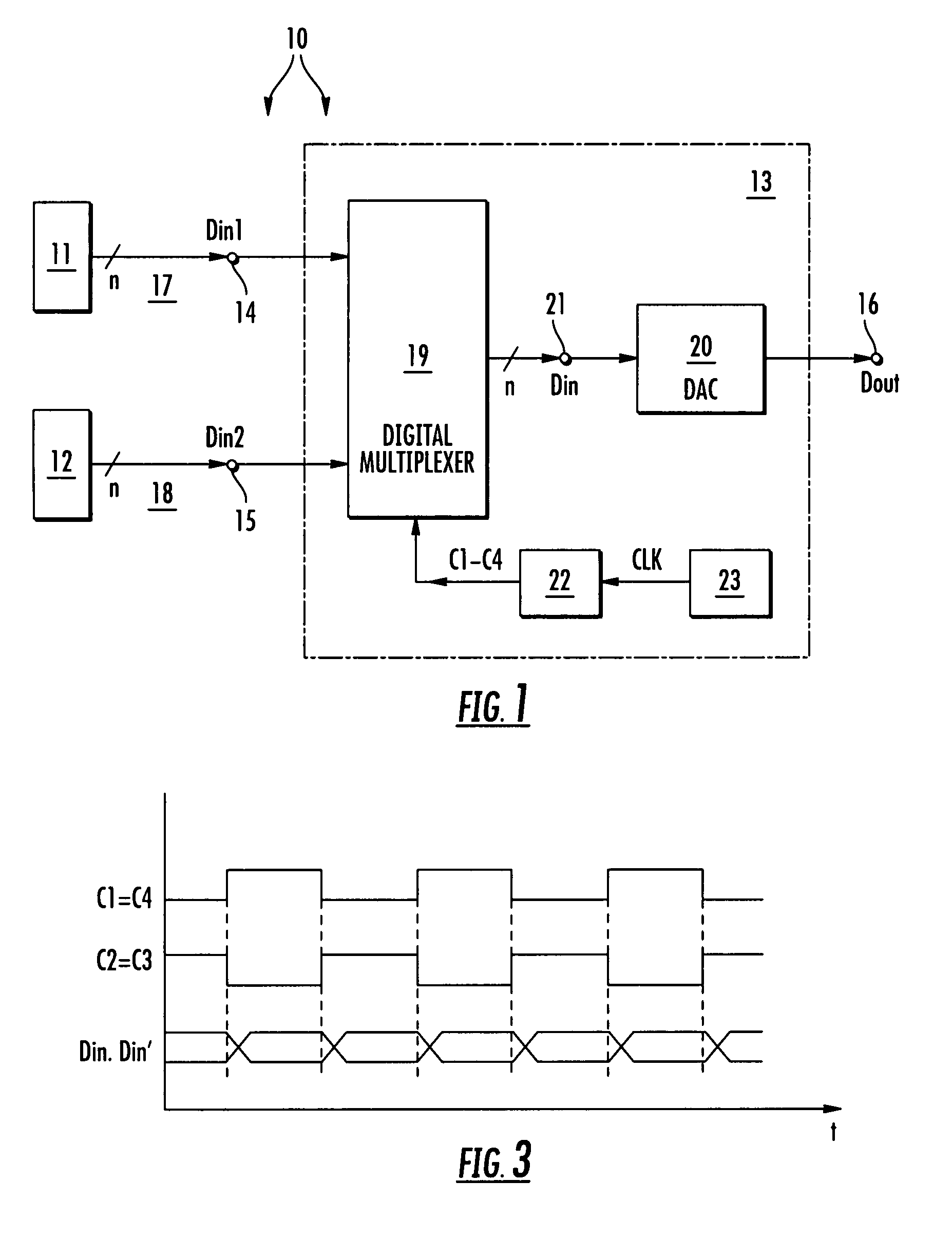
[0024]FIG. 1 shows a general system with a digital / analog converter arrangement according to the invention by means of a block diagram. The system in FIG. 1, which is there designated by the reference symbol 10, can be, for example, any communication system or any computer- or software-based system. In the present exemplary embodiment, the system 10 contains two data sources 11, 12 and an n-bit digital / analog converter arrangement 13 according to the invention. The digital / analog converter arrangement 13 has two data inputs 14, 15 and a data output 16. One of the data sources 11, 12 in each case is connected to one of the data inputs 14, 15.

[0025]Each of the data sources 11, 12 is designed for providing at its output end digital data signals Din1, Din2 of bit width n which can be coupled into the downst...


PUM


Abstract

A multi-channel digital / analog converter arrangement comprises at least two data channels for receiving and forwarding a corresponding number of digital data input signals comprising respective time characteristics, a digital multiplexer generating a digital intermediate signal present at a common node by combining the at least two digital data input signals, and a digital / analog converter connected downstream of the multiplexer for converting the digital intermediate signal into an analog output signal. The multiplexer comprises a tuning device for tuning the time characteristics of the at least two digital data input signals in respect to each other.

Description

BACKGROUND OF THE INVENTION[0001]The invention relates to a multi-channel digital / analog converter arrangement.[0002]A digital / analog converter, for short also called D / A converter in the text which follows, is designed for converting a digital, for example a binary input signal into an analog output signal, for example an output voltage or an output current. Regarding the general background of D / A converters, reference is made to U.S. Pat. Nos. 6,346,901 B1, 4,712,091 and 5,293,166.[0003]D / A converters are mainly used in digital signal processing. Applications for digital signal processing are, for example computer- and software-based applications, for example in a microprocessor, or telecommunication applications, for example broadband applications or mobile radio applications. In modern systems of digital signal processing there is an increasing requirement for processing greater and greater volumes of data in shorter and shorter time. With the advancing development in the field ...

Claims


Application Information

Patent Timeline
Patent Type & Authority Patents(United States)
IPC IPC(8): H03M1/66
CPCH03K17/005H03M1/662H03M1/742H03M1/661
Inventor DRAXELMAYR, DIETER
Owner INFINEON TECH AG
Learn More