
Dryer for a recording medium

a recording medium and drying machine technology, applied in the direction of drying machines with progressive movements, photosensitive materials, furnaces, etc., can solve the problems of affecting the drying effect, so as to prevent the effect of defective carrying

Inactive Publication Date: 2006-07-18
FUJIFILM CORP +1
View PDF3 Cites 5 Cited by
  • Summary
  • Abstract
  • Description
  • Claims
  • Application Information

AI Technical Summary

Benefits of technology

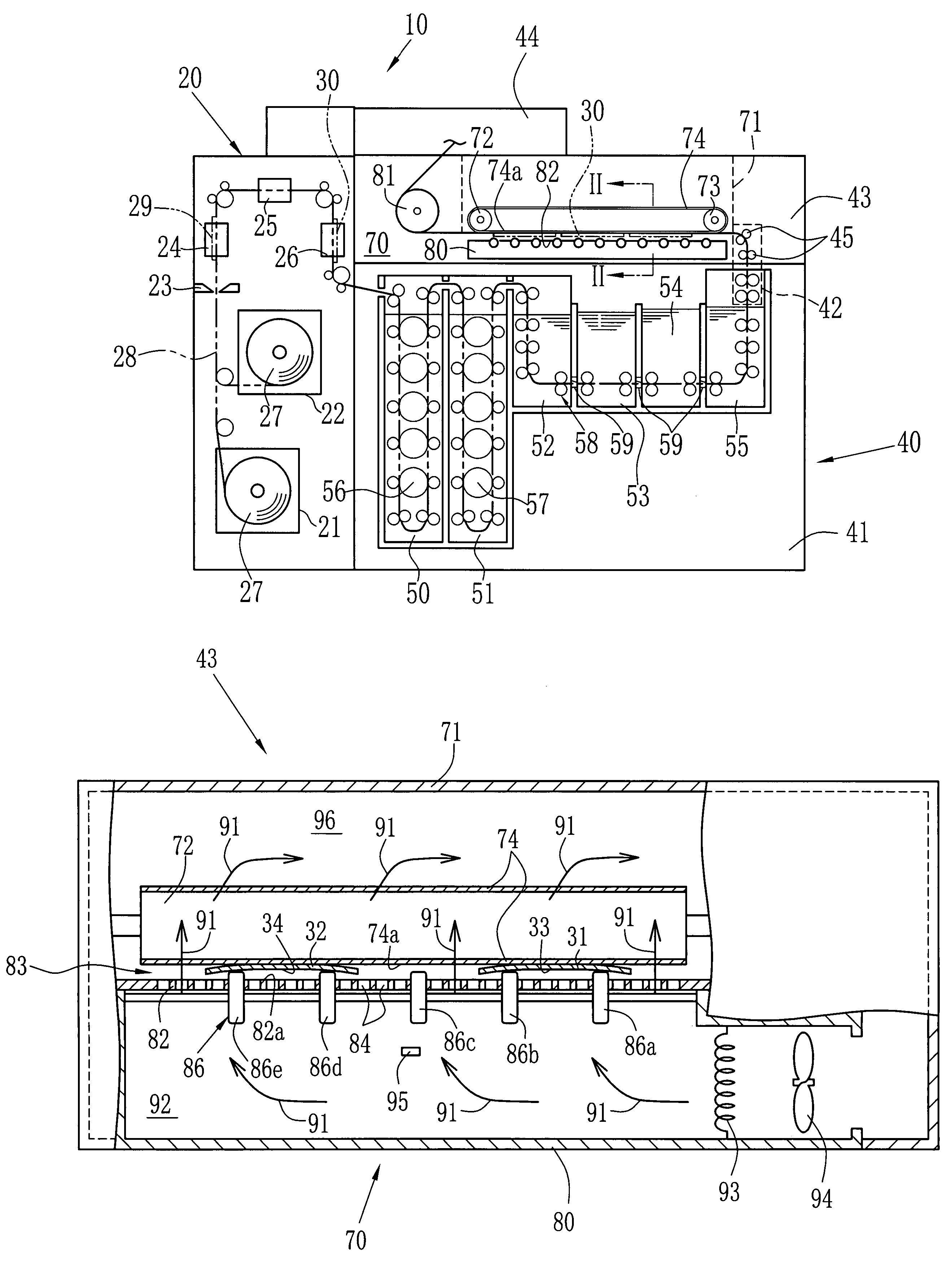
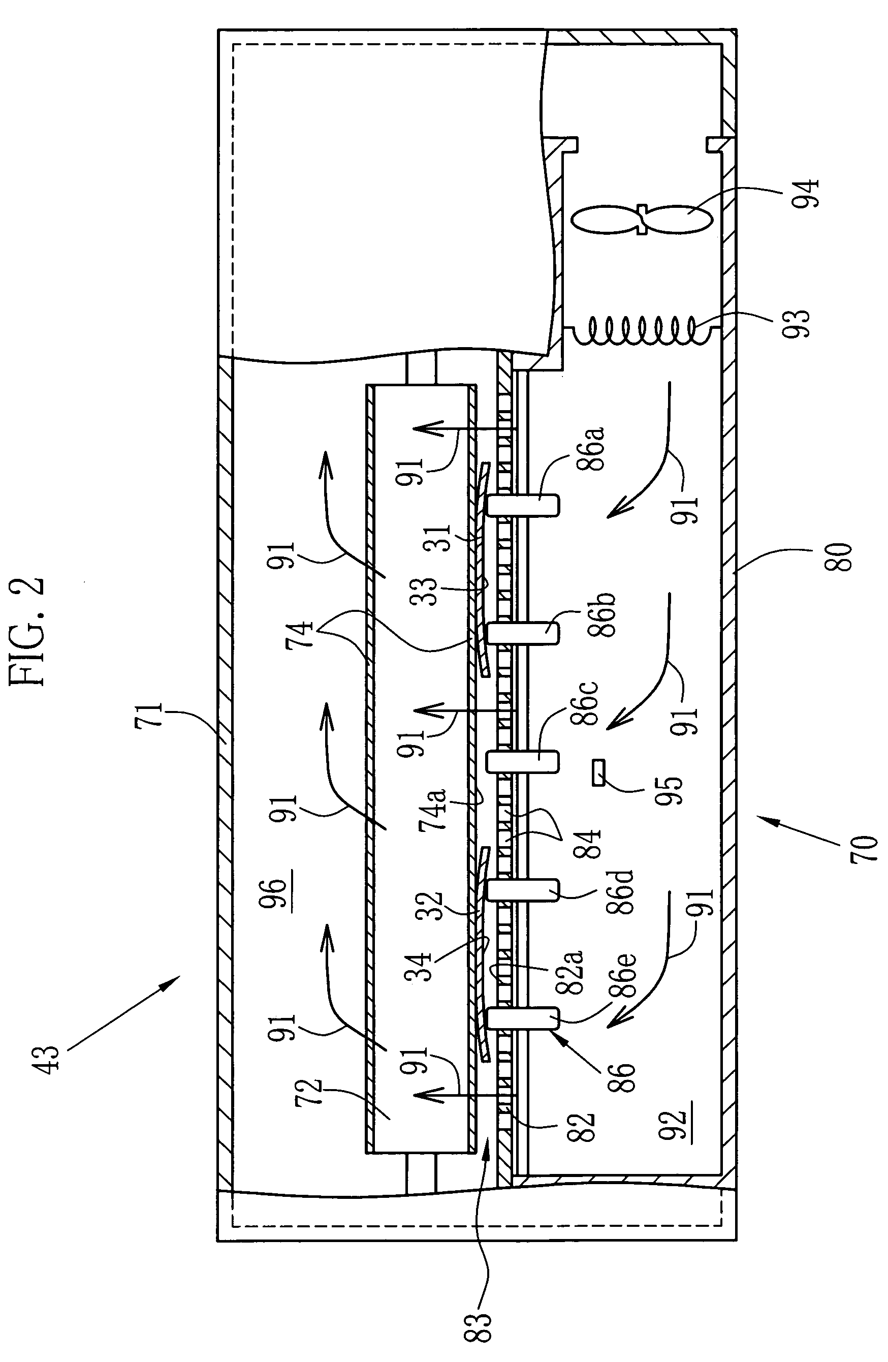
The present invention provides a dryer for a recording medium that has a reduced number of guide rollers to effectively perform a levitation carry of the recording medium. The dryer also prevents abrasions and dirt from occurring on the photosensitive emulsion surface. The dryer includes a guide plate, conveyor, and guide rollers. The wet recording medium is dried by jetting dry air while carried in a passage. The guide plate is disposed along the passage and at a position confronting the recording medium. The guide plate has jet holes for jetting the dry air towards the recording medium. The conveyor carries the recording medium along the passage. The recording medium is separated from the guide plate by the dry air jetted from the jet holes. The guide roller partially projects into the passage through the guide plate. The dryer satisfies certain conditional expressions. The conveyor is an endless belt laid between two rollers, with exhaust openings through which the dry air passes. The dryer further comprises a blower and a heater. Both edges of the recording medium are prevented from coming into contact with a surface of the guide plate to prevent defective carry.

Problems solved by technology

If a degree of curling becomes large, both edges of the photosensitive sheet are likely to come into contact with the guide plate, and the defects of abrasions, dirt and so forth are likely to be caused on the emulsion surface.
Further, if a corner of the photosensitive sheet is caught by a nozzle, it becomes impossible to perform aligned carry, since a carry position is disarrayed.
In addition, jamming is sometimes caused.
However, in the Publication No. 8-76346, since a lot of the skewer rollers are arranged, a number of the jet holes is limited.
Thus, there arises a problem in that the blower is enlarged for the purpose of keeping necessary levitation force of the photosensitive sheet.

Method used


Image

  • Dryer for a recording medium
  • Dryer for a recording medium
  • Dryer for a recording medium

Examples


Embodiment Construction

)

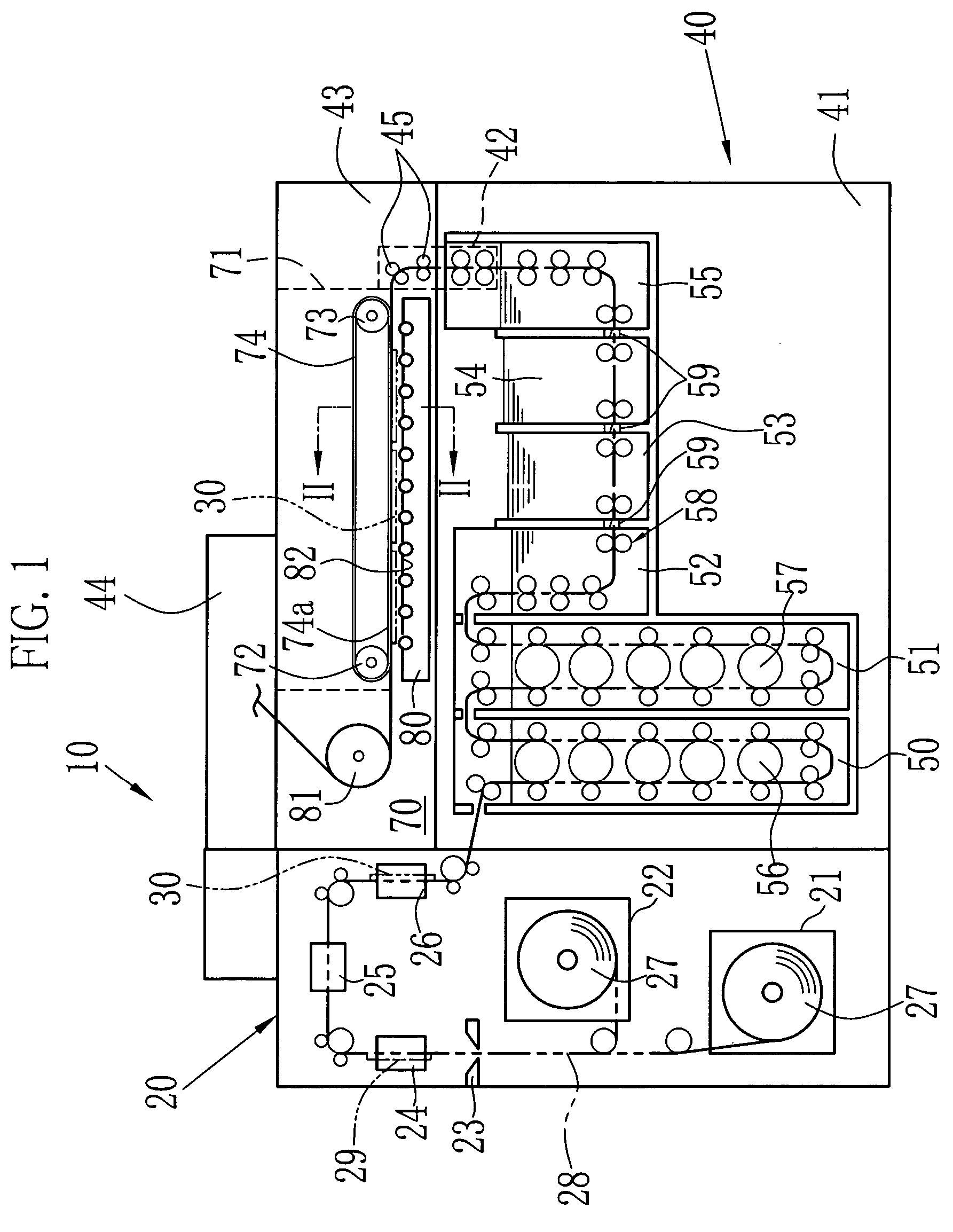
[0019]FIG. 1 schematically shows an inner structure of a printer processor 10 comprising a dryer according to the present invention. The printer processor 10 comprises a printer section 20 and a processor section 40. The printer section 20 includes magazines 21 and 22, a cutter 23, a back-printing unit 24, an exposure unit 25 and a sorter 26. A photosensitive material 27 having a strip shape is wound and set in each of the magazines 21 and 22. The photosensitive material 27 is carried toward the exposure unit 25 along a passage 28 shown by a chain double-dashed line. The cutter 23 cuts the photosensitive material 27 into a photosensitive sheet 29 in accordance with a print size. The back-printing unit 24 prints a frame number, correction data and so forth on a rear surface. The exposed photosensitive sheets 30 are sorted by the sorter 26 into a single row or into plural rows in accordance with the print size. And then, the exposed photosensitive sheet 30 is carried to the processor...


PUM


Abstract

Dry air is jetted from jet holes of a guide plate toward a conveyor belt to levitate a photosensitive sheet and to press it against the conveyor belt. The photosensitive sheet is supported and carried by the conveyor belt. The dry air dries the photosensitive sheet. A projection amount h of a guide roller projecting from the guide plate is defined so as to satisfy an expression of h≧H×(W−P) / W. H is a gap between the guide plate and the conveyor belt. P is a length from a center line of the carried photosensitive sheet to an outer edge of the guide roller. W is a length from the center line to a lateral end of the photosensitive sheet. Even if a curl occurs on the photosensitive sheet, an edge thereof is prevented from contacting with the guide plate.

Description

BACKGROUND OF THE INVENTION[0001]1. Field of the Invention[0002]The present invention relates to a dryer for a recording medium, and in particular to a dryer for drying a recording medium of a wet photosensitive material and so forth.[0003]2. Description of the Related Art[0004]In an automatic processor of a printer processor and so forth used in a photographic laboratory or the like, a photosensitive material of a photographic paper and so forth is cut by a cuter in accordance with a print size, and print processing is executed for the cut-sheet-shaped photosensitive material (hereinafter, called as a photosensitive sheet). After the print processing, the photosensitive sheets are sorted into a single row or into plural rows by a sorter, and then, are carried to a developing equipment. In general, the developing equipment is provided with carry rollers for carrying the photosensitive sheet, and processing baths containing processing solutions for color development, bleaching / fixing...

Claims


Application Information

Patent Timeline
Patent Type & Authority Patents(United States)
IPC IPC(8): G03D13/00G03D3/08F26B13/10G03D15/02
CPCG03D15/022
Inventor YOSHIDA, FUTOSHI
Owner FUJIFILM CORP
Learn More