
Apparatus for depositing a packing unit at a desired position on a load carrier

a technology of a load carrier and a packing unit, which is applied in the direction of special packaging, pile separation, packaging goods type, etc., can solve the problems of limiting the profitability of the logistics system, requiring skilled and experienced workers, and time-consuming manual pallet loading

Inactive Publication Date: 2006-05-23
LOGISTIK INFORMATIK
View PDF10 Cites 48 Cited by
  • Summary
  • Abstract
  • Description
  • Claims
  • Application Information

AI Technical Summary

Benefits of technology

"The present invention provides an apparatus and method for automatically loading load carriers with packing units. The apparatus includes a lifting device for lifting and lowering the load carrier, a loading aid for supporting the packing units, and a stabilizing film for forming a stable load stack. The method involves determining a three-dimensional loading configuration of the packing units, lifting the packing units onto the load carrier, and depositing them in the position determined by the loading configuration. The invention enables full automation of the loading process, reduces costs, and increases loading capacity."

Problems solved by technology

Manual pallet loading is therefore time-consuming, requires skilled and experienced workers and is a factor limiting the profitability of the logistics system.
The manual loading of load carriers with occasionally heavy packing units under ergonomically unfavourable conditions is moreover bad for the health of the workers engaged in loading.
The drawback of this is, however, that vacuum grippers are usable only with smooth and stable materials and lateral gripping arms may easily slide off or cause damage to delicate packaging.
What is more, the use of laterally applied gripping arms inevitably leaves gaps between the packing units in the loading stack on the load carrier, thereby preventing optimum utilization of space and stability owing to the gaps left between the packing units.

Method used


Image

  • Apparatus for depositing a packing unit at a desired position on a load carrier
  • Apparatus for depositing a packing unit at a desired position on a load carrier
  • Apparatus for depositing a packing unit at a desired position on a load carrier

Examples


Embodiment Construction

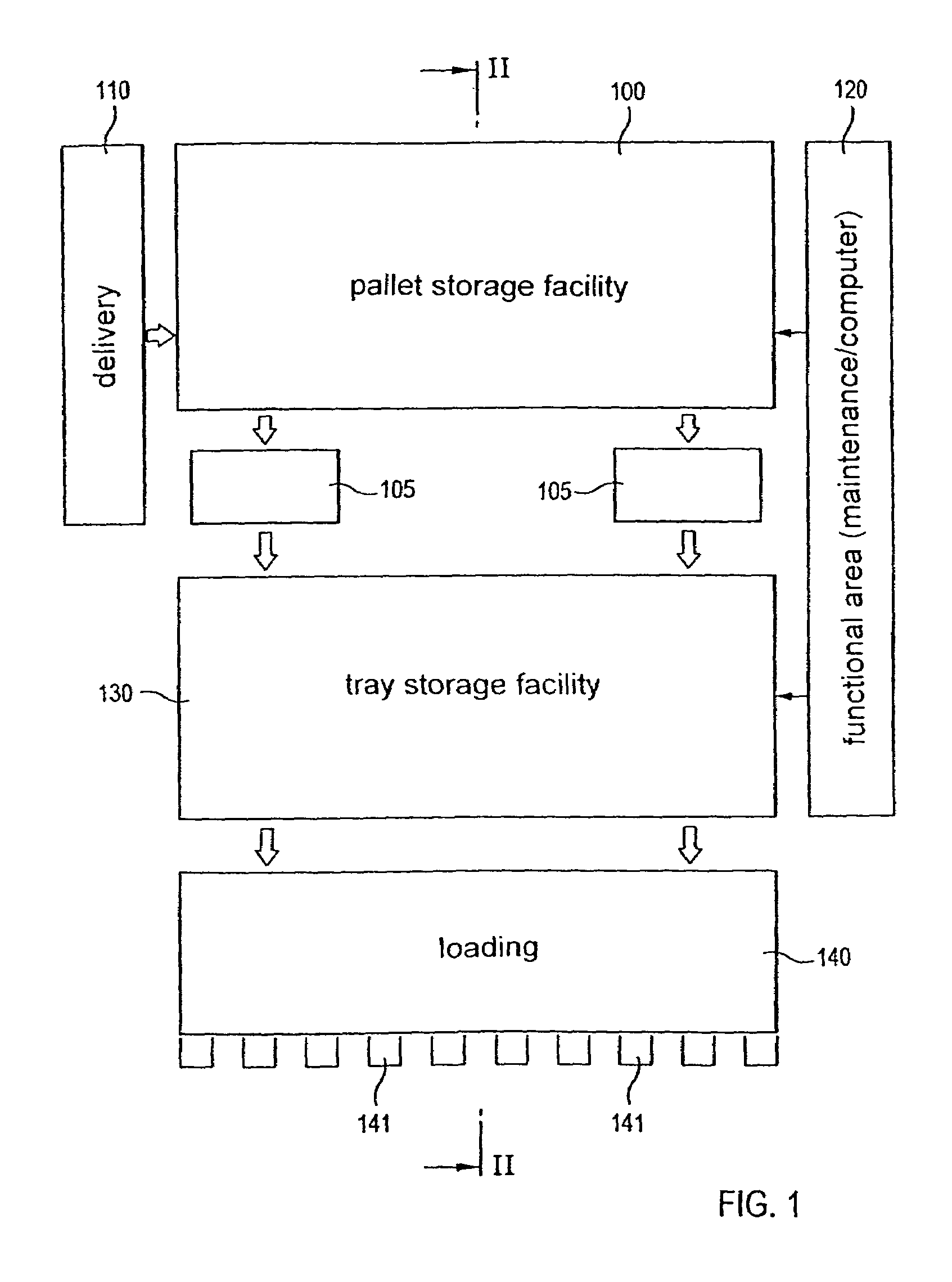
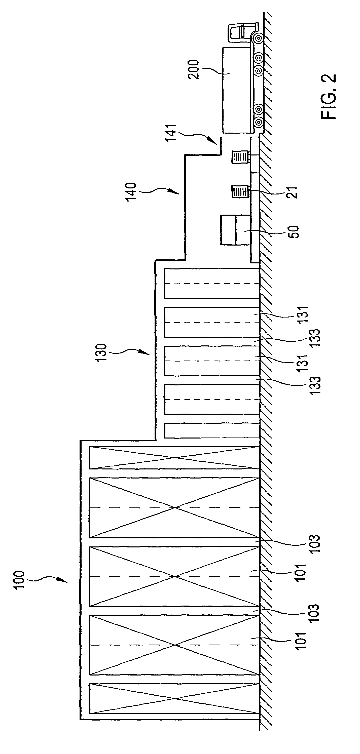
[0035]FIG. 1 shows in plan view an embodiment of a rack storage facility, to which the invention is applicable, and FIG. 2 shows a cross-sectional view along the line II—II of FIG. 1 of the rack storage facility.

[0036]The rack storage facility 100 is designed as a pallet storage facility, i.e. the articles or goods delivered to a delivery station 110 are stored on the delivery pallets in the pallet storage facility or input storage facility in rack rows 110. In a known manner rack-mounted storage / retrieval machines are movable in the aisles 103 formed between the rack rows 101 (see FIG. 2) and store the delivered storage pallets in the rack storage facility. Connected by an automated conveying system to the rack storage facility is a tray storage facility 130, which in turn comprises storage racks 131, which are separated by aisles 133 and in which the articles to be stored are stored on trays. According to the embodiment illustrated in FIG. 2 the tray storage, facility 130 has a lo...


PUM


Abstract

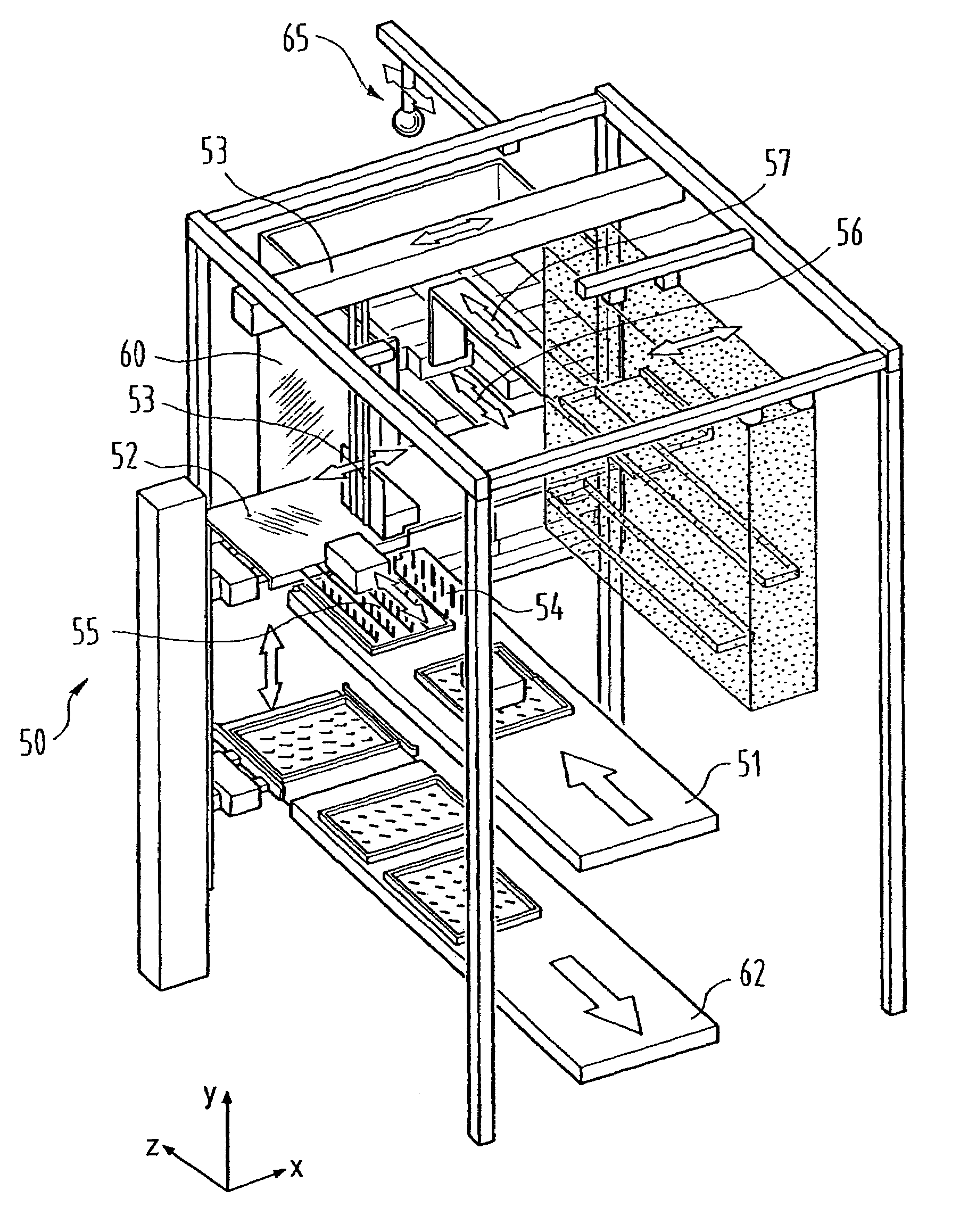
A machine for loading a load carrier (20) such as a pallet with packing units (cardboard boxes, collis etc.), which form a load stack (21) on the load carrier, is presented. The machine includes handling and support mechanism (52–57), that allows a packing unit (15) to be loaded. The handling and support mechanism supports the load from below throughout the operation of loading from a feed device (51) onto the load stack. By virtue of the handling and support mechanism, the packing unit may be deposited at any selectable spatial position on the load stack. It is therefore possible to form an optimized load stack on the load carrier in which the packing units are always supported from below, with the result that the loading is not dependent upon the material quality of the packaging of the packing unit.

Description

FIELD OF THE INVENTION[0001]The invention relates to an apparatus and a method of loading a load carrier such as e.g. a pallet with packing units, which form a load stack on the load carrier.TECHNICAL BACKGROUND[0002]In the development of logistics systems there is a trend towards an ever greater degree of automation in order to save costs and time and increase the profitability of the systems. Storage into, and retrieval from, a high-rise installation is therefore frequently effected by automated, computer-controlled rack-mounted storage / retrieval machines. In the output area of a storage system the articles required for an order are loaded onto a means of transport, such as a lorry. For many applications, such as e.g. in the retail trade, a delivery order comprises a plurality of different articles which are loaded by means of load carriers, such as e.g. pallets provided with rollers, onto lorries which deliver them to the individual branches.[0003]Loading the load carriers and / or...

Claims


Application Information

Patent Timeline
Patent Type & Authority Patents(United States)
IPC IPC(8): B65B35/50B65G57/22B65G65/02B65G1/137B65G57/03
CPCB65G1/1378B65G57/03B65G57/22Y10S414/116B65G2201/0261B65G2201/0267
Inventor WINKLER, WALTER
Owner LOGISTIK INFORMATIK
Learn More