
Process for producing a component from metal

Active Publication Date: 2006-05-02
AB SKF
View PDF10 Cites 1 Cited by
  • Summary
  • Abstract
  • Description
  • Claims
  • Application Information

AI Technical Summary

Benefits of technology

[0007]Therefore, one object of the invention is to increase the service life of the component by stabilizing the dislocation state. Another object is to provide a method that represents an advance in the art.
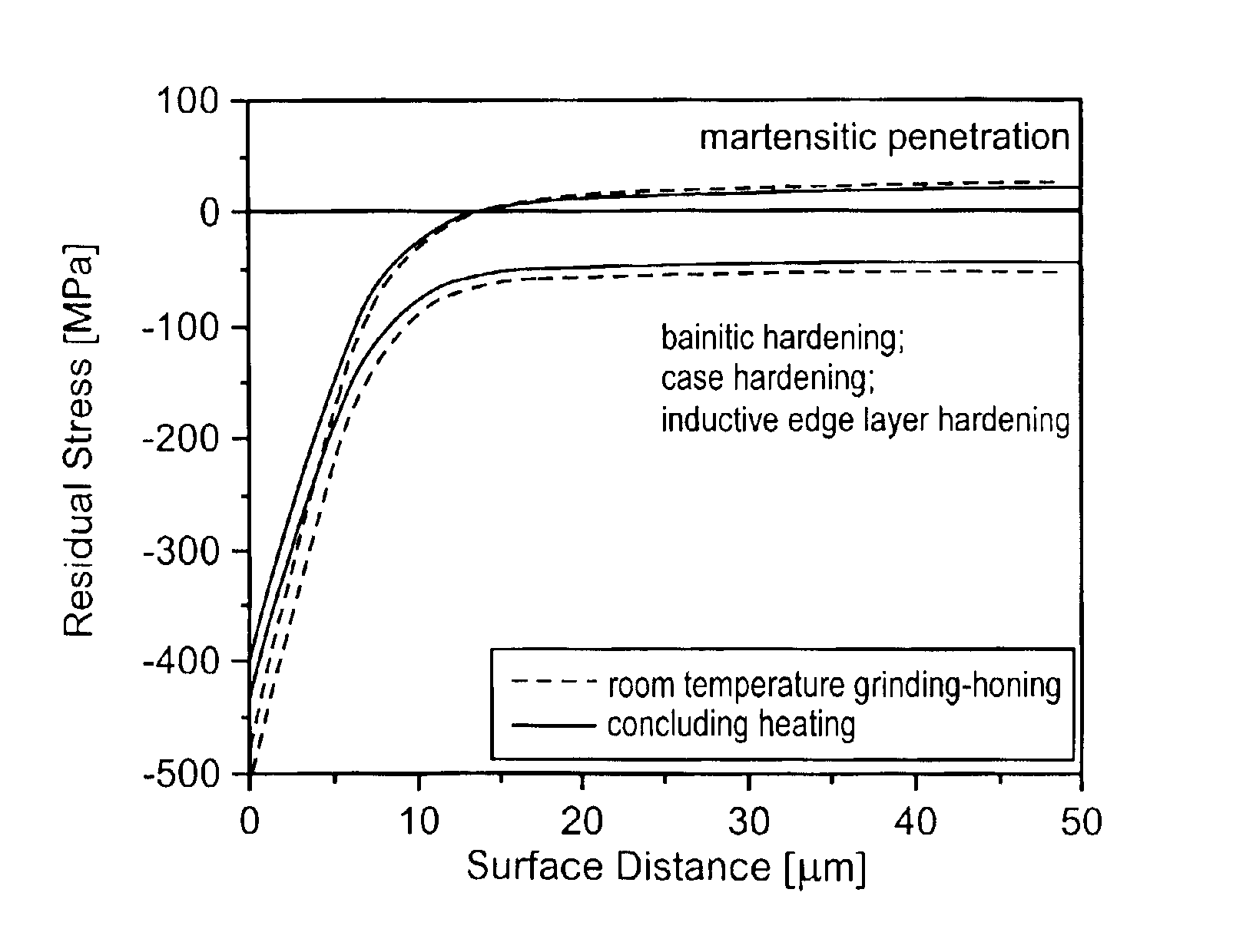
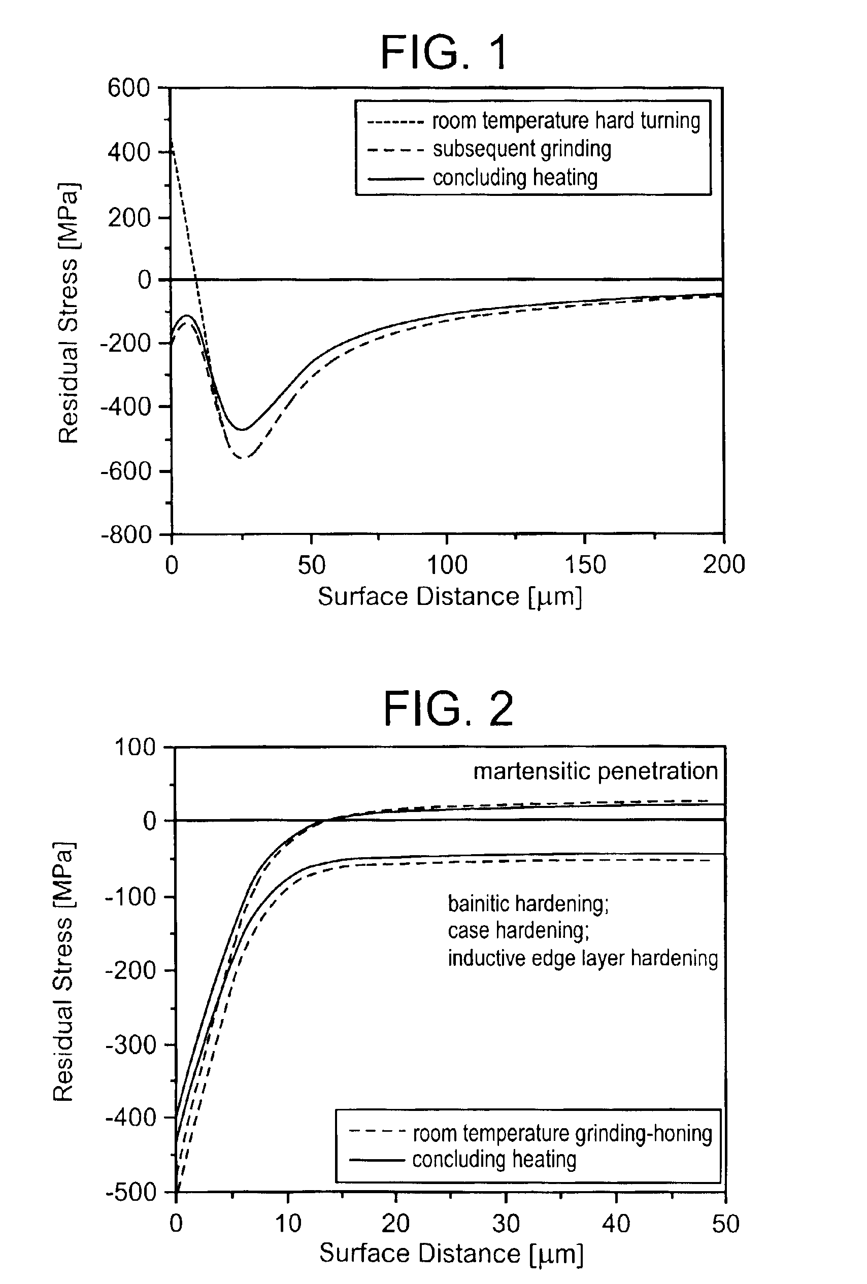
[0020]Following the surface machining (see step b), in metallic materials with dissolved interstitial atoms, the heating of the component stabilizes the dislocation structure which has been produced in the edge zone when compared to corresponding pure room temperature treatments. Particularly in steels, the interstitially dissolved carbon becomes mobile in the lattice and can diffuse onto the dislocation cores with the formation of so-called Cottrell clouds (diffusion lengths typically in the range of a few dozen nanometers) and segregate there (compare Protevin-Le Chatelier effect, strain ageing). This atom arrangement is favorable in terms of energy, and thus supports the resistance of the dislocation structure which has been produced by surface machining in the plastically deformed edge zone and counteracts the incipient dislocation motion during operation. By increasing the fatigue resistance (fatigue strength) of the material the service life is thus increased. In addition, stabilization of the residual compressive stress state which has been introduced by the surface machining at room temperature in the surface layer takes place, the peak being reduced by up to roughly 10% to 20%, depending on the temperature and the duration. In doing so, optionally multistage surface machining can be carried out at room temperature, such that after its complete termination, no residual tensile stresses have been produced in the mechanically influenced edge zone. These residual stresses would adversely affect the fatigue behavior of the material.

Problems solved by technology

Thus, stabilization of the residual compressive stress state which is introduced with suitably completed surface treatments is not achieved either.

Method used


Image

  • Process for producing a component from metal
  • Process for producing a component from metal

Examples


Embodiment Construction

[0026]The foregoing and additional features and characteristics of the present invention will become more apparent from the following detailed description considered with reference to the accompanying drawing figures in which like reference numerals designate like elements.

[0027]The drawings show embodiments of the invention. FIGS. 1 and 2 show diagrams, the residual stress of a metallic component being plotted on the y-axis and the surface distance being plotted on the x-axis.

[0028]The invention can be used to produce a metallic component with a long service life. Further, a high dislocation density is produced by surface machining, such as hard turning, milling, grinding, honing and grinding, at room temperature in the plasticizing material area with a varied extent depending on the process. With suitable process control (for example, up-cut milling, hard turning with a suitable cutting edge geometry), in addition residual compressive stresses, which inhibit cracks, are formed in ...


PUM

PropertyMeasurementUnit
Temperatureaaaaaaaaaa
Areaaaaaaaaaaa

Abstract

A process for producing a component of metal includes a) carrying out a heat treatment to harden the component, which ends with a heating process, especially with a tempering or microstructural transformation process, at a given temperature (TE); b) carrying out at least machining of the component at room temperature (TU) in order to provide its desired geometrical shape; and c) subsequent heating of the component to a temperature (T) which is greater than room temperature (TU).

Description

[0001]This application is based on and claims priority under 35 U.S.C. § 119 to German Application No. 102 09 264.8 filed on Mar. 1, 2002, the entire content of which is incorporated herein by reference.FIELD OF THE INVENTION[0002]The invention relates to a process for producing a component from metal.BACKGROUND OF THE INVENTION[0003]In the description of the background of the present invention that follows reference is made to certain structures and methods, however, such references should not necessarily be construed as an admission that these structures and methods qualify as prior art under the applicable statutory provisions. Applicants reserve the right to demonstrate that any of the referenced subject matter does not constitute prior art with regard to the present invention.[0004]One such process is described in DE 39 10 959 C2. It is provided there that the metallic component is first subjected to heat treatment to harden the part. Heat treatment ends with an tempering proce...

Claims


Application Information

Patent Timeline
IPC IPC(8): C21D9/36C21D9/00C21D1/06C21D1/18C21D1/20C21D1/34C21D1/42C21D9/32C21D9/40
CPCC21D1/18F16C33/64C21D1/20C21D9/32Y10S148/906C21D2261/00F16C2240/18C21D9/40
Inventor GEGNER, JURGEN
Owner AB SKF
Learn More