
Apparatus and method for acquiring phase lock timing recovery in a partial response maximum likelihood (PRML) channel

a phase lock and recovery technology, applied in the field of applicability and method of acquiring phase lock timing recovery in a digital channel, can solve the problems of head oscillation between read and write functions, no common signal processing platform, and affecting both device development and commercial availability, so as to mitigate latency issues, facilitate processing, and tolerate latency issues.

Inactive Publication Date: 2006-01-24
AVAGO TECH WIRELESS IP SINGAPORE PTE
View PDF7 Cites 9 Cited by
  • Summary
  • Abstract
  • Description
  • Claims
  • Application Information

AI Technical Summary

Benefits of technology

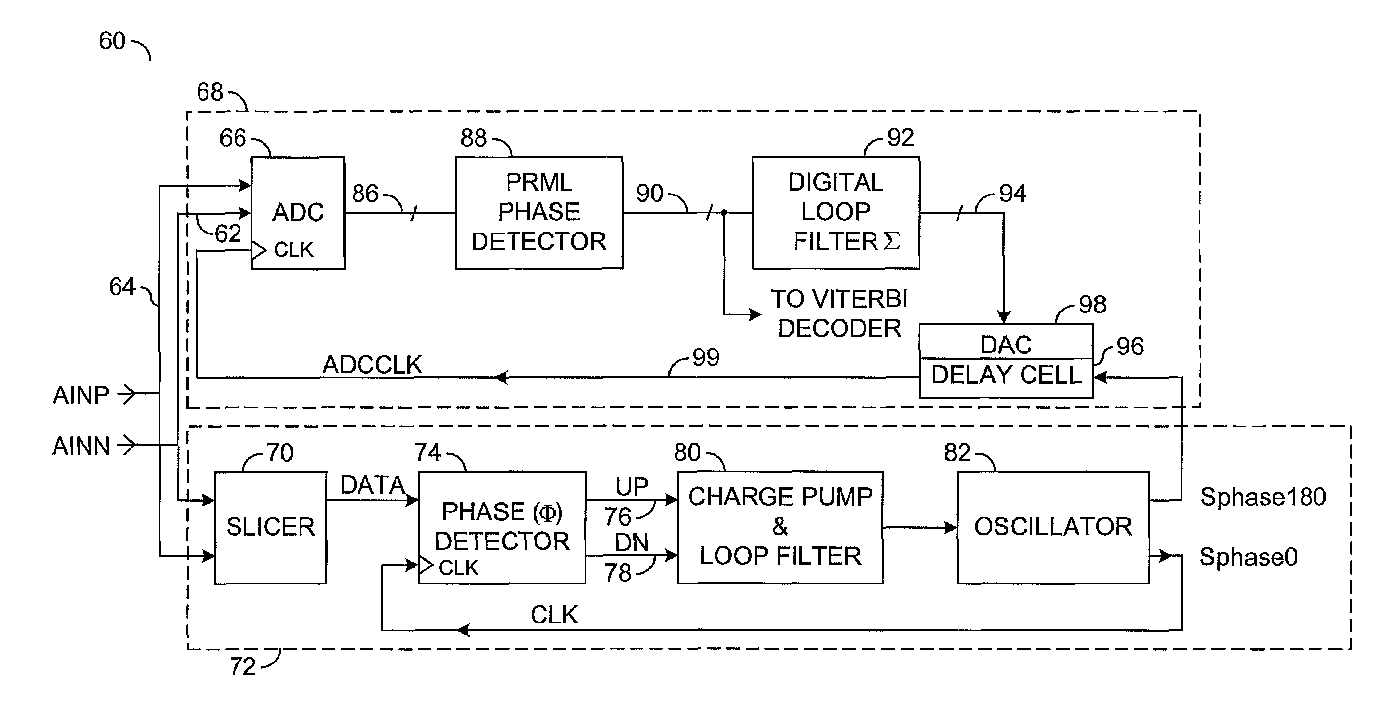
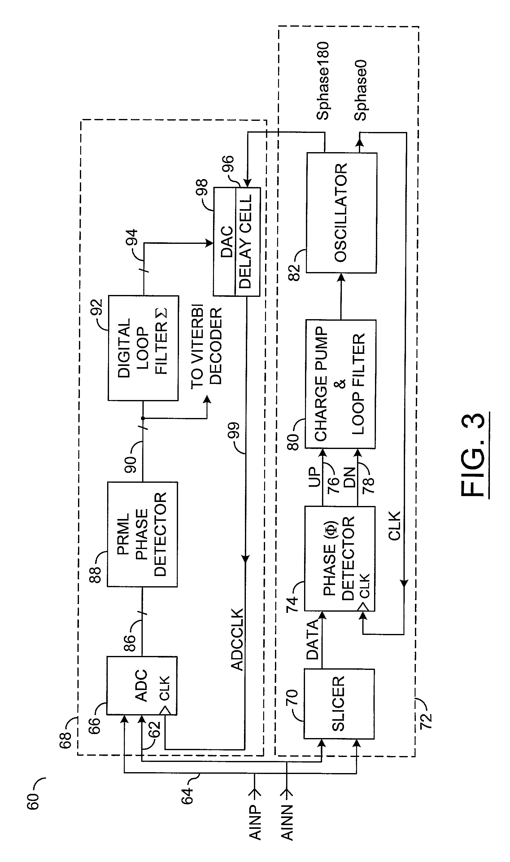
"The present invention relates to a method for acquiring phase lock in a digital channel with a digital feedback loop. The method involves applying a data signal to an analog phase lock loop (PLL) having a plurality of operational poles and a single output. The output is then applied to a digital delay lock loop (DLL) having a single pole. The delay constant of the DLL is adjusted to compensate for variations in phase between the data signal and the output signal. The method can be used in a system that supports a partial response maximum likelihood processing technique. The invention also includes a phase acquisition circuit and a digital to analog converter for use in the system. The technical effects of the invention include improved phase lock acquisition and improved signal processing in the digital channel."

Problems solved by technology

A significant issue, however, arises with internal signal processing requirements of such DVD and CD ROM machines, namely that the signal processing required to support certain formats and ever-increasing operating speeds differs according to the optical formatting of the disc.
Consequently, there is no common signal processing platform.
In another example, with respect to DVD RAM read-write, a technical issue that has affected both device development and commercial availability relates to head oscillation between read and write functions.
Taking into account stabilization times and a general noise environment, the provision of DVD RAM at 4× and beyond is technically demanding.
Unfortunately, with increased speed, there are reduced operational margins and hence a likelihood of increased error rates.
In other words, while the noise floor remains ostensibly constant, the ability to resolve information bearing “pits” (supporting, for example, eight-fourteen modulation, efm) becomes increasing more difficult.
Clearly, any inability to recover or write information in an accurate fashion results in loss or corruption of data.
Unfortunately, PRML (while having wide applicability in both radio and optical channels) places significant demands on processing and circuit overhead, since PRML, as will be understood, requires the use of flash converters, Viterbi decoders, etc.
Digital PLL processing can be quite complex and encompass a digital loop filter that contributes “latency” to the feedback path of the PLL.
Indeed, the conventional use of digital components (in the digital PLL required for PRML) results in a high degree of latency in processing.
It is well known that high levels of latency in feedback systems leads to instability, particularly where high gain is introduced to the scheme in order to achieve, for example, acceptable lock acquisition capture ranges in the case of PLLs.
In other words, in practical terms, the high degree of latency causes the PLL to exhibit poor phase margin, with this adversely affecting an ability of the digital PLL to acquire stabilisation.
The problem can be further exasperated by the need to include some form of equalizer and pipelined A-to-D converter architecture in the timing recovery feedback loop.
Consequently, with a digital PLL, an ability to drive the digital loop with high gain, required for a good / acceptable capture range, is unfortunately significantly restricted.
Furthermore, the analog PLL inherently exhibits less latency, but is unable to provide a digitally sampled sequence.

Method used


Image

  • Apparatus and method for acquiring phase lock timing recovery in a partial response maximum likelihood (PRML) channel
  • Apparatus and method for acquiring phase lock timing recovery in a partial response maximum likelihood (PRML) channel
  • Apparatus and method for acquiring phase lock timing recovery in a partial response maximum likelihood (PRML) channel

Examples


Embodiment Construction

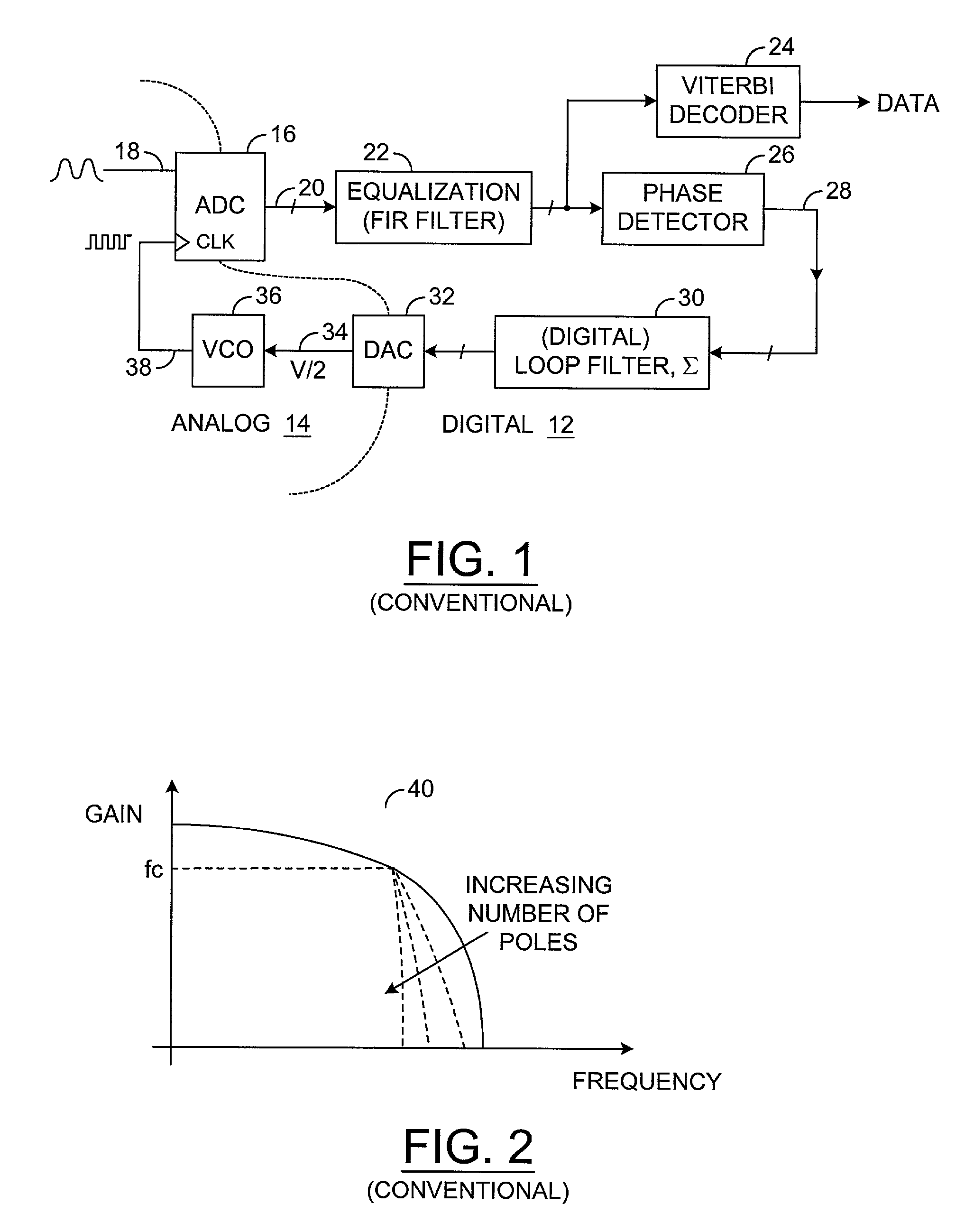
[0042]For a complete understanding, reference is initially made to FIG. 1 that shows a schematic block diagram of a conventional PRML (digital) PLL 10. The PRML PLL 10 includes digital circuitry 12 and some analog circuitry 14. An analog to digital converter (ADC) 16 receives an analog waveform 18 as a first input. A sample sequence 20 (in the form of a parallel data word) is output from the ADC 16, with the sample sequence 20 applied to equalization circuitry 22, such as an FIR filter. An output from the equalization circuitry is applied both to a Viterbi decoder 24 for data recovery and also to a phase detector 26. A phase error control word 28 is communicated via a loop filter (Σ) 30 to a digital to analog converter (DAC) 32. Typically, the loop filter 30 employs an accumulator or summer, which is itself realized with a feedback path in which an output from a clocked flip-flop is combined with an input to the flip-flop. An output 34 from the DAC 32 is applied to a voltage control...


PUM

PropertyMeasurementUnit
phaseaaaaaaaaaa
frequencyaaaaaaaaaa
input currentaaaaaaaaaa

Abstract

The present invention is a method of acquiring phase lock to a data signal in a digital channel having a digital feedback loop. The method generally comprises: (A) applying the data signal to an analog phase lock loop configured to have (i) at least two poles and (ii) presend intermediate output signal frequency locked to the data signal; (B) applying the data signal and the intermediate output signal to the digital channel; and (C) adjusting a delay constant for the digital feedback loop to (i) compensate for variations in phase between the data signal and the intermediate output signal and (ii) acquire phase lock by using a single pole in the digital channel.

Description

[0001]This application claims the benefit of United Kingdom Application No. 0028532.3 filed Nov. 21, 2000.FIELD OF THE INVENTION[0002]This invention relates, in general, to an apparatus and method for acquiring phase lock timing recovery in a digital channel. The present invention is particularly, but not exclusively, applicable to the provisioning of a delay locked loop (DLL) scheme for an optical device, such as a digital versatile disc (DVD) supporting random access memory (RAM) or read only memory (ROM) applications, where the digital channel is subject to partial response maximum likelihood (PRML) data recovery techniques.BACKGROUND OF THE INVENTION[0003]There are several competing formats for optical data storage. The formats are essentially DVD ROM, compact disc (CD) ROM, and DVD read-write (RW) plus and minus. There is also DVD RAM that has optical read capabilities, as well as optical DVD RAM write. A significant issue, however, arises with internal signal processing requir...

Claims


Application Information

Patent Timeline
Patent Type & Authority Patents(United States)
IPC IPC(8): H03D3/24G11B20/14H03L7/07H03L7/081H03L7/099
CPCG11B20/10055G11B20/1426H03L7/07H03L7/0995H03L7/0812
Inventor WILLIAMS, STEPHEN
Owner AVAGO TECH WIRELESS IP SINGAPORE PTE
Learn More