
Method for the absorptive outward transfer of ammonia and methane out of synthesis gas

a technology of ammonia and methane, which is applied in the field of ammonia preparation/separation, inorganic chemistry, and the use of liquid separation agents, can solve the problems of reducing the yield obtained in the reaction system, requiring a long refrigeration cycle, and reducing the operating pressure of the solvent, so as to increase the quantity of nh3 evaporated, reduce the operating pressure, and increase the operating temperature of the solvent

Inactive Publication Date: 2006-01-24
UHDE GMBH
View PDF12 Cites 0 Cited by
  • Summary
  • Abstract
  • Description
  • Claims
  • Application Information

AI Technical Summary

Benefits of technology

[0016]The absorption step may either be part of a conventional scrubbing in which the liquid solvent comes directly into contact with the synthesis gas, but it may also take place in devices in which said solvent does not directly come into contact with the synthesis gas. In a further embodiment of the invention the absorption step takes place in a contactor equipped with a diaphragm suitable to partition the gas side from the liquid side and permeable to the gas components but impermeable to the solvent, so that the solvent does not come into direct contact with the synthesis gas. This method has a special advantage because it definitely prevents the penetration of solvent into the synthesis gas so that the steam pressure required for the solvent decreases accordingly vis-à-vis that needed for scrubbing, thereby improving the viscosity and the solubility in NH3 and CH4 of the solvent. An additional advantage of this method is that the diaphragm has a substantially larger contact surface with regard to volume than that provided for processes with direct contact of solvent and synthesis gas. It is recommended that the diaphragm be arranged in one or several contactors of modular type and be designed as capillary components conveying the solvent. In comparison to the solvents known to be used for diaphragm contactors according to, for example, EP 0 751 815 B1 the homologues of alkylene glycol-alkyl-ether exhibit a major advantage of lower viscosity, a fact that really permits cost-effective conveyance through capillary components and this constitutes an advantage of the invention.
[0017]A further embodiment of the invention provides for solvent regeneration in at least three process steps. When implementing this configuration in a plant for NH3 production from synthesis gas it is recommended that the solvent first passes through the arrangement of at least three process steps designed to reduce the operating pressure and, optionally, increase the operating temperature of the solvent so that the dissolved gases are removed, said steps being called flashing steps. The solvent then flows through a downstream rectification step and a regeneration step operated at atmospheric or negative pressure. The first flashing step is used to reduce the pressure of the laden solvent to a value that permits evaporation of H2-rich gas from the solvent. The second step provides for flashing to a pressure that is suited for the development of CH4-rich gas and the third step for a further pressure reduction permitting the development of NH3 vapour. This configuration enables the generation of three gas streams which represent and advantage of the invention. The H2-rich gas stream, for example, can be recycled to the NH3 synthesis system or exploited as heating agent and the CH4-rich stream, for example, is suitable for recycling to the plant for generation of NH3 synthesis gas or exploitable for heating.
[0018]Further generation of the solvent or of a part-stream thereof is effected by thermal regeneration implemented as rectification, preferably in two steps: first at a pressure above the atmospheric pressure so that the vapours from the column are condensable by an economic method and subsequently below the atmospheric pressure or partial vacuum. This can be turned to an advantage by compressing the vapours to such an extent that it becomes condensable together with the vapours from the upstream regeneration steps. The last regeneration step carried out under partial vacuum alternatively can be implemented as flashing step. A further embodiment of the invention provides for the feed of the desorbed NH3 vapour to the intake side of a coolant compressor. The liquid NH3 obtained in the coolant compressor is exploited as reflux for the upstream rectification step.
[0019]When supplying larger amounts of heat to the flashing steps it is possible to increase the quantity of NH3 evaporated from the solvent. In this case it is an advantage to re-use low-temperature heat, particularly waste heat from other process steps. It is also possible to implement the flashing steps in a split mode, i.e. decreasing the pressure in a first individual step and raising the temperature in a second.
[0020]In a further embodiment of the invention the compressed NH3 vapour is scrubbed with the aid of liquid NH3 from a refrigeration system and is subsequently recycled to a cold flashing step, so that solvent losses are avoided. Said refrigeration unit can be beneficially integrated into the regeneration process.
[0021]A further embodiment of the invention provides for a regeneration of the solvent using inert gas. The stripping agent required can be flash gas withdrawn from the process itself or heating gas taken from synthesis gas loop or steam generation unit upstream of the NH3 synthesis process.

Problems solved by technology

In order to provide for the condensation of a further NH3 portion of the non-reacted gas mixture, additional cooling to much lower temperatures is required, hence an expensive refrigeration cycle.
But this system has the disadvantage that, for example, the NH3 separation at 180 bar synthesis pressure can be efficiently carried out down to a residual content of about 4 molar % only.
Another disadvantage is that an expensive method is required to separate further NH3 from the purge stream withdrawn if its exploitation is not abandoned.
But when the said rate is kept low, the inerts such as CH4 are enriched in the loop synthesis gas and their partial pressure reduces the yield obtained in the reaction system and the portion of NH3 that can be recovered with the aid of cooling water.
This, however, involved on the one hand the problem to remove the dissolved NH3 from said solution, on the other hand the need to avoid volatilisation of fractions of the aqueous solution during scrubbing, said fractions entering the synthesis gas and thus causing technical problems in the downstream equipment, for example, poisoning of the catalyst.
The said problems aroused the technological prejudice that there is not a safe and economic method to separate the NH3 from the synthesis gas by scrubbing.
Various alkylene glycol solvents have been suggested but in view of operational problems and related efficiency setbacks, said process has never achieved a breakthrough on the market for over 30 years.
Patent WO 90 / 08736 A1 describes a further process of this type but on account of poor efficiency of this system in NH3 synthesis plants operated at a loop pressure of >100 bar, this process also failed on the market.

Method used


Image

  • Method for the absorptive outward transfer of ammonia and methane out of synthesis gas
  • Method for the absorptive outward transfer of ammonia and methane out of synthesis gas
  • Method for the absorptive outward transfer of ammonia and methane out of synthesis gas

Examples


Embodiment Construction

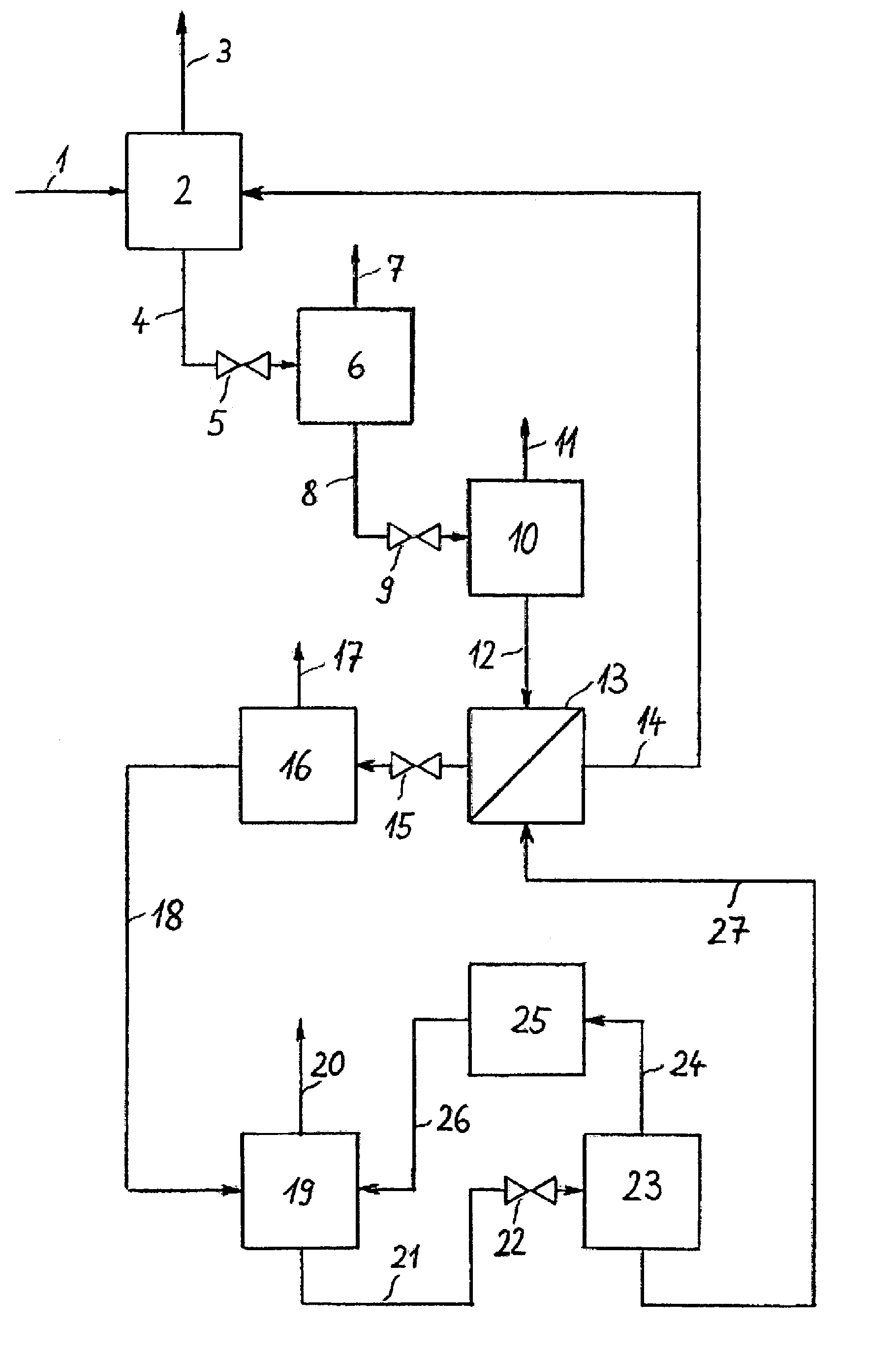
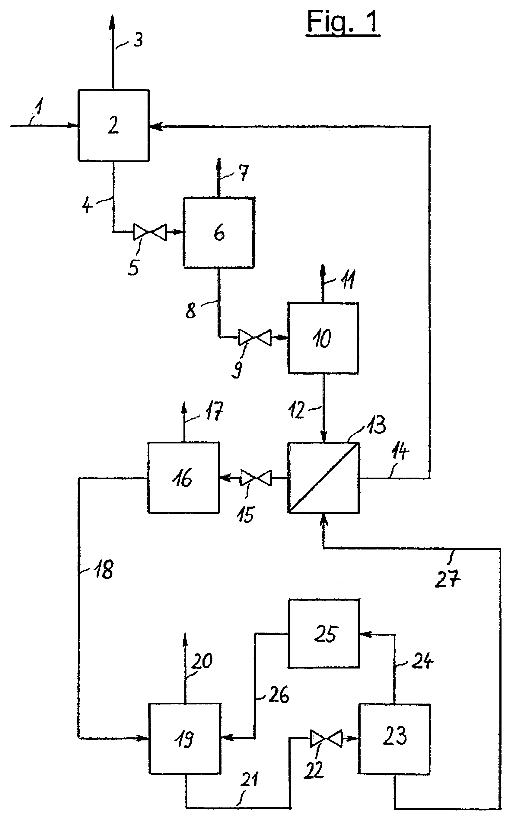
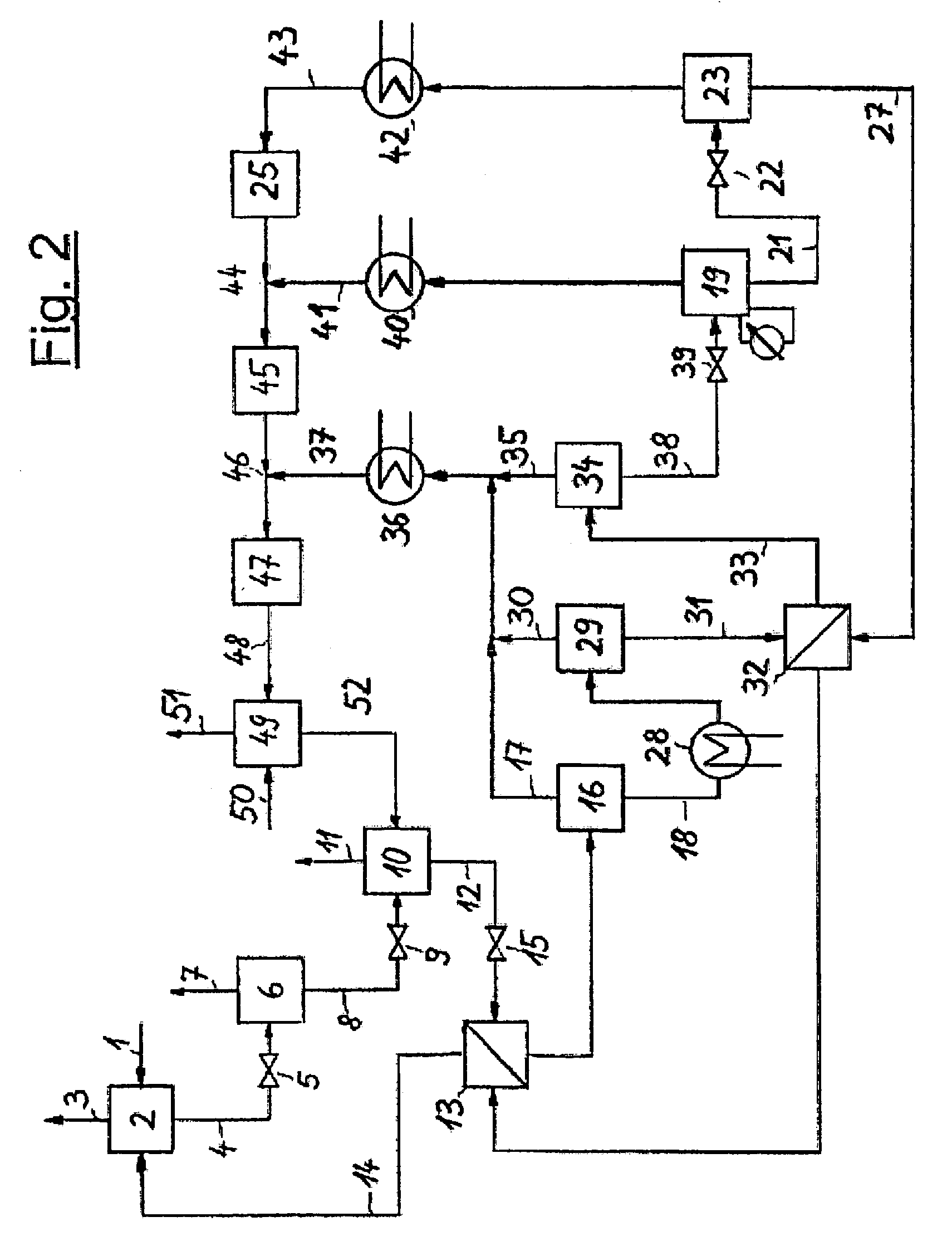
[0026]The invention is illustrated in the three PFDs which show a typical configuration. FIG. 1 depicts the invented process which includes an absorption step, several pressure reducing units and a regeneration system for the solvent in a multi-stage desorption. It is possible to provide various locations for NH3 absorption in the NH3 production process and, optionally, several absorption devices may be arranged in a single plant section. The representation of just one absorption step is shown in FIG. 1 and FIG. 2, hence, is to be understood that several absorption steps may exist and that the regeneration of solvent and the NH3 recovery described in this document may also be combined for all absorption steps.

[0027]NH3-rich synthesis gas 1 is fed at a pressure of approx. 180 bar (abs.) to absorption step 2 in which NH3 is absorbed by a solvent. NH3-lean synthesis gas 3 is withdrawn from absorption step 2 and piped to a downstream unit not represented in the diagram. Laden solvent 4 ...


PUM

PropertyMeasurementUnit
temperatureaaaaaaaaaa

Abstract

The invention relates to a process for the absorptive separation of NH3 and CH4 from a gas under high pressure, which at least contains NH3, H2, N2 and CH4, using a high-boiling, physically acting and regenerable solvent which contains homologues of alkylene glycol-alkyl-ether and which also may contain water, the absorbed components NH3, H2, N2 and CH4 being separated from the laden solvent in at least two further process steps at different pressure rates, thereby withdrawing at least one NH3-rich and at least one CH4-rich gas fraction from the solvent. This process is particularly suitable to be incorporated as unit in an ammonia production plant.

Description

[0001]This application is a 371 of International Application No. PCT / EP02 / 03812, filed on Apr. 5, 2002.BACKGROUND OF THE INVENTION[0002]The invention relates to a process for the absorptive separation of NH3 and CH4 from a gas under high pressure (>50 bar abs.), which at least contains NH3, H2, N2 and CH4, hereinafter referred to as synthesis gas. NH3-rich synthesis gas is chiefly available in processes for generating NH3 from such synthesis gas, the conversion rate of said processes being really low because of the temperatures, pressures and catalysts that are applied, and the NH3 produced from synthesis gas having to be removed from a non-reacted gas stream. It is pointed out, however, that the invention is by no means restricted to this specific application.[0003]Conventional plants for generating NH3 from synthesis gas are designed as loop systems operating at high pressure. Said configuration provides for the compression of the synthesis gas that contains H2, N2 and inert ga...

Claims


Application Information

Patent Timeline
Patent Type & Authority Patents(United States)
IPC IPC(8): B01D53/14C01C1/04B01D53/00B01D53/22C01B3/02C01B3/50C01B3/52
CPCB01D53/1425B01D53/1493B01D53/229C01B3/025C01B3/501C01B3/52C01C1/0476Y02C20/20C01B2203/0415C01B2203/0465C01B2203/048C01B2203/146C01B2203/0405Y02P20/129Y02P20/52
Inventor WYSCHOFSKY, MICHAELLIU, VINCENT
Owner UHDE GMBH
Learn More