
SMA actuator with improved temperature control

a technology of sma wire and temperature control, which is applied in the direction of mechanical equipment, hot gas positive displacement engine plants, electric devices, etc., can solve the problems of limited commercial actuator applications, short cycle life, and damage to sma wires, and achieves faster response, shorter cycle time, and greater cooling of sma wires

Inactive Publication Date: 2006-01-03
ALFMEIER PRAZISION BAUGRUPPEN & SYSTLOSUNGEN
View PDF73 Cites 45 Cited by
  • Summary
  • Abstract
  • Description
  • Claims
  • Application Information

AI Technical Summary

Benefits of technology

[0021]The improved temperature control in these actuators provides greater cooling of the SMA wires for a faster response (shorter cycle time) of the actuators and, because overheating and consequent fatiguing of the wires can be avoided, also provides an extended working life for the actuators.

Problems solved by technology

Although SMAs have been known since 1951, they have found limited commercial actuator applications due to some inherent limitations in the physical processes which create the shape memory properties.
However, it can only sustain a few cycles at this strain level before it fails.
Unfortunately SMA wires can be damaged if they are routed around sharp bends.
The addition of a large number of small pulleys makes a system mechanically complex, eliminating one of the attractions of using SMA in the first place.
If this cooling is achieved by convection in still air, then it can take many seconds before the actuator can be used again.
The problems of cycle time are exacerbated when the SMA actuator is subjected to repeated on-off cycling, such as if it were used in a Stiquito or similar toy or in another environment where the actuator is constantly cycled.
Then, the air and any other components around the SMA elements may well become heated above external ambient temperature, resulting in a reduced ability of the SMA elements to release heat and cool to the martensitic state.
Working life (number of cycles) can also be adversely affected by the inability to control cooling, as rapid heating to achieve fill contraction can often result in the temperature of the SMA wire considerably exceeding the Af temperature, particularly over the central portion of the wire; and such repeated large temperature excursions cause fatigue in the wire and loss of working life.
Clearly, in many applications, especially where miniaturization is desired, it is impractical to use long straight wires.
Coils, although greatly increasing the stroke delivered, are bulky and significantly decrease the available force (the force is proportional to the sine of the pitch angle—the angle between the axis of the coil as a whole and the axis of a single turn of the coil—and that may be as low as a few degrees); and, to compensate for the drop in force, thicker wires are used which reduce the responsiveness of the resulting actuator, making it unsuitable for many applications.
Other mechanisms commonly used to mechanically amplify the available displacement, such as those disclosed in D. Grant, V. Hayward, “Variable Control Structure of Shape Memory Alloy Actuators”, IEEE Control Systems, 17(3), 80-88 (1997) and in U.S. Pat. No. 4,806,815, suffer from the same limitation on available force, again leading to the requirement for thicker wires and the attendant problems with cycle time.
Also, because current flow in an SMA wire tends (as with all solid conductors) to be concentrated at the surface of the wire, there is the risk of “hot-spots” and uneven heat distribution, reducing the life of the wire.
Similarly, on cooling substantially no change in length occurs above Ms, and substantially no further change in length occurs below Mf; however, there is typically substantial hysteresis in the length-temperature curve.

Method used


Image

  • SMA actuator with improved temperature control
  • SMA actuator with improved temperature control
  • SMA actuator with improved temperature control

Examples


example

A Miniature Stroke Multiplying Actuator

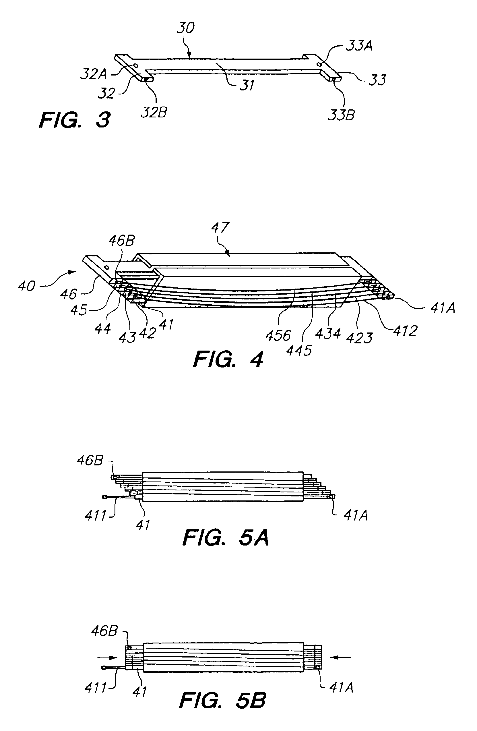
[0069]FIG. 9 shows in exploded view the assembly, shown generally at 91, of the plates and wires of this embodiment, and the frame 92 onto which the plates are assembled. These plates will be stacked into a parallel array on the frame, with plate 911 being the lowest, followed in succession by plates 912 through 916, and topped by plate 917. Each plate is made of a material that is rigid yet soft enough to permit crimping of the material onto the SMA wires 921 through 926 at crimp joints 911A and 912B through 916A and 917B respectively without damaging the wires (excessive compression of the SMA wires causes fragility and change in transition properties). A suitable material for the plates is a half hard cartridge brass, or a half hard “nickel silver” alloy. Other methods of attachment of the wires may be used, but crimping is an attractive method for ease, economy, and not increasing the size of the assembled actuator. Lowermost plate 911, whi...


PUM

PropertyMeasurementUnit
Lengthaaaaaaaaaa
Fractionaaaaaaaaaa
Fractionaaaaaaaaaa

Abstract

A SMA actuator having rigid members and SMA wires, in which improved temperature control of the SMA wires of the actuator is provided by a heat sink, which may be the rigid members themselves, in close proximity to at least a central portion of the wires. Optionally, the heat sink is sized and placed such that the end portions of the wires where they are attached to the rigid members are not in close proximity to the heat sink. Where the heat sink is external, it optionally has a cooling element that acts passively as a heat sink during the heating cycle of the actuator and that acts as an active cooling element during the cooling cycle of the actuator. An SMA actuator having a desired contraction limit and a power supply circuit has a switch in the power supply circuit that is normally closed when the actuator is contracted to less than the desired contraction limit and is opened by the actuator reaching the desired contraction limit. This improved temperature control provides greater cooling of the SMA wires for a faster response and an extended working life of the actuator.

Description

CROSS-REFERENCE TO RELATED APPLICATION[0001]This application claims the priority under 35 USC 119(e) of Provisional Application No. 60 / 270,985, filed Feb. 22, 2001, the disclosure of which is incorporated by reference into this application.BACKGROUND OF THE INVENTION[0002](a) Field of the Invention[0003]This invention relates to shape-memory alloy (SMA) actuators. In particular, this invention relates to SMA actuators, especially miniaturizable SMA actuators, with improved temperature control for faster response and extended working life.[0004](b) Description of Related Art[0005]A class of materials was discovered in the 1950s that exhibit what is known as the shape memory effect. See, for example, K. Otsuka, C. M. Wayman, “Shape Memory Materials”, Cambridge University Press, Cambridge, England, 1998, ISBN 0-521-44487X. These materials exhibit a thermoelastic martensite transformation; i.e. they are pliable below a certain transition temperature because the material is in its marten...

Claims


Application Information

Patent Timeline
IPC IPC(8): F01B29/10F03G7/06
CPCF03G7/065F05C2225/08F03G7/0614F05B2280/5006
Inventor VON BEHRENS, PETER E.FAIRBANKS, DYLAN M.
Owner ALFMEIER PRAZISION BAUGRUPPEN & SYSTLOSUNGEN
Learn More