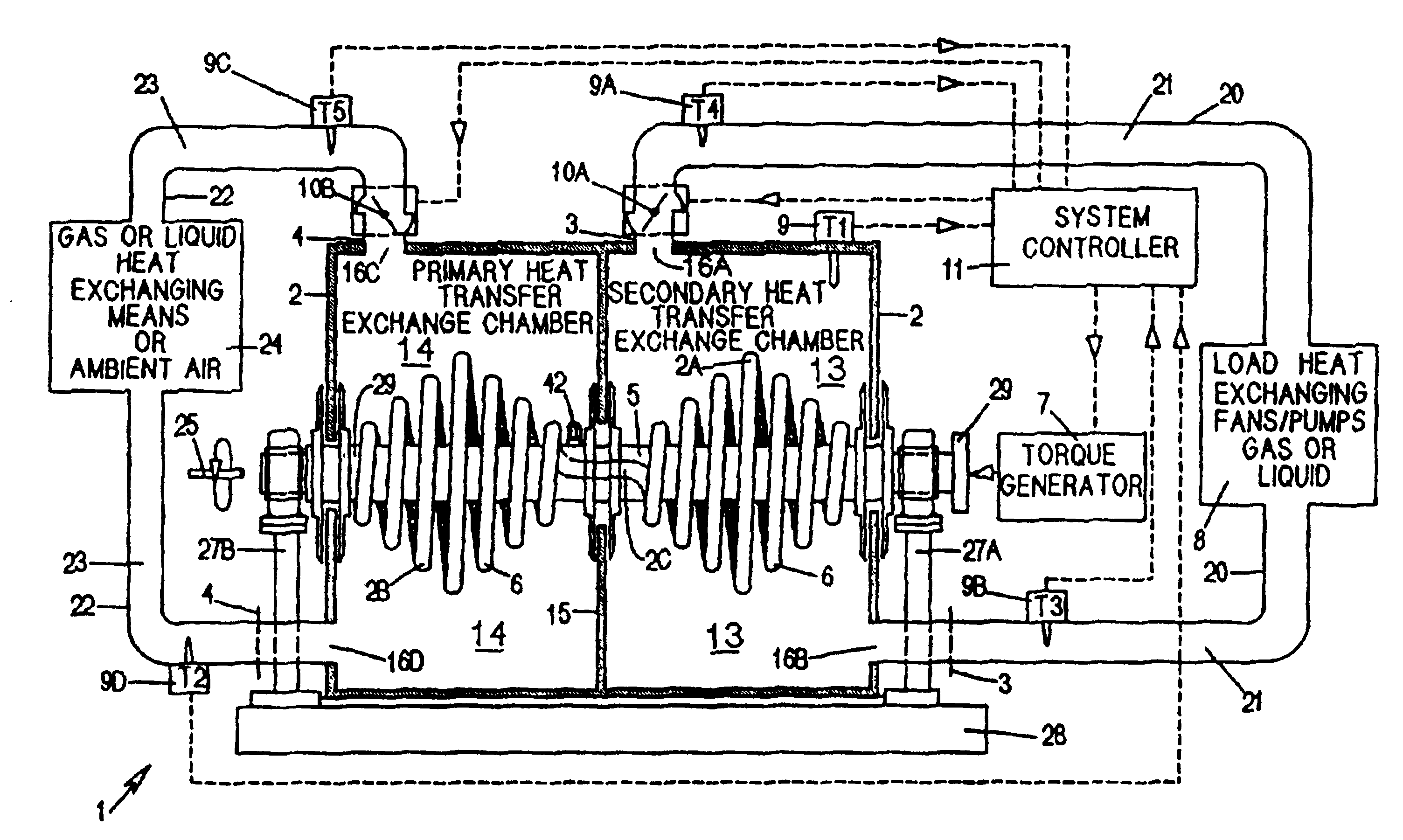
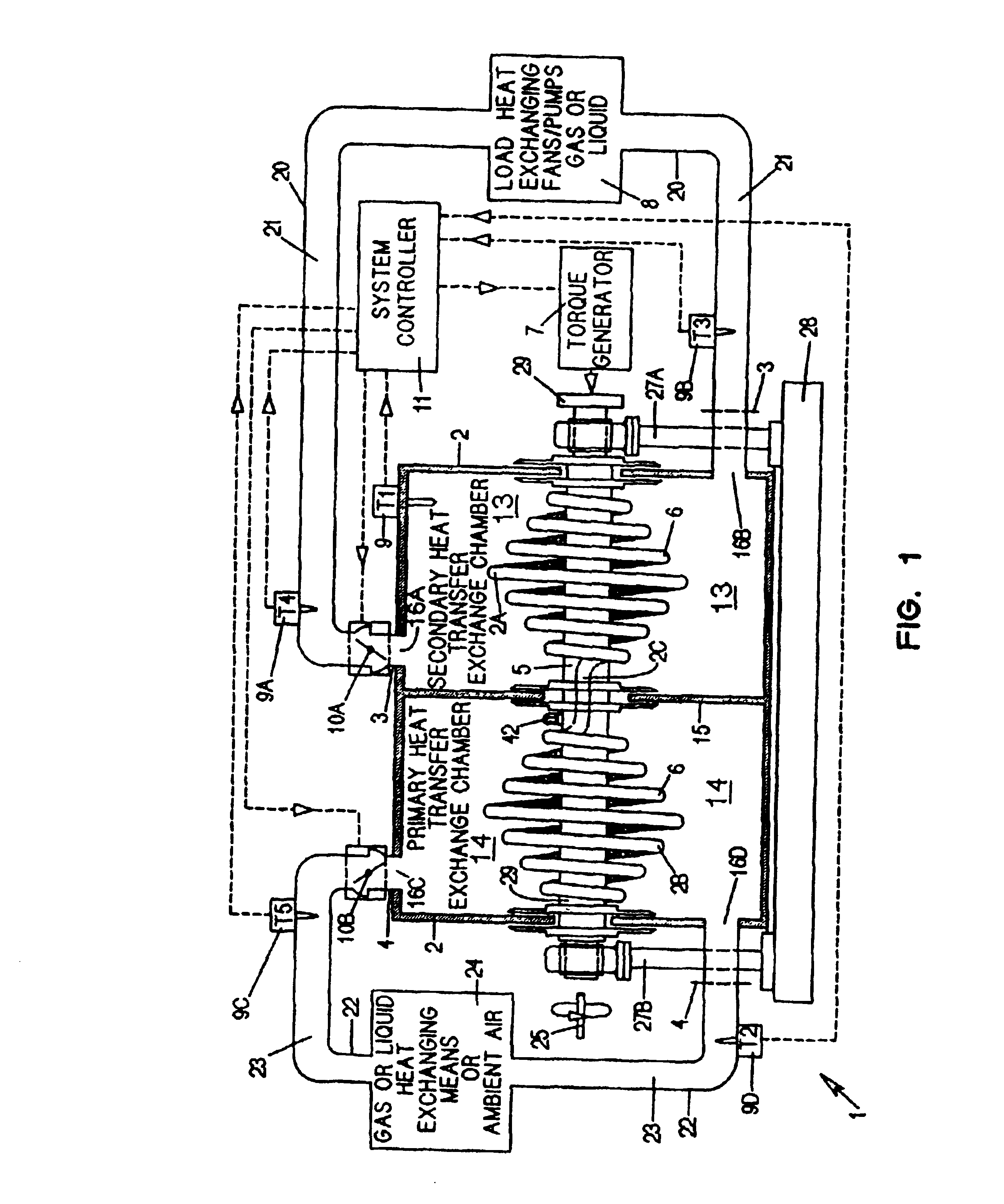
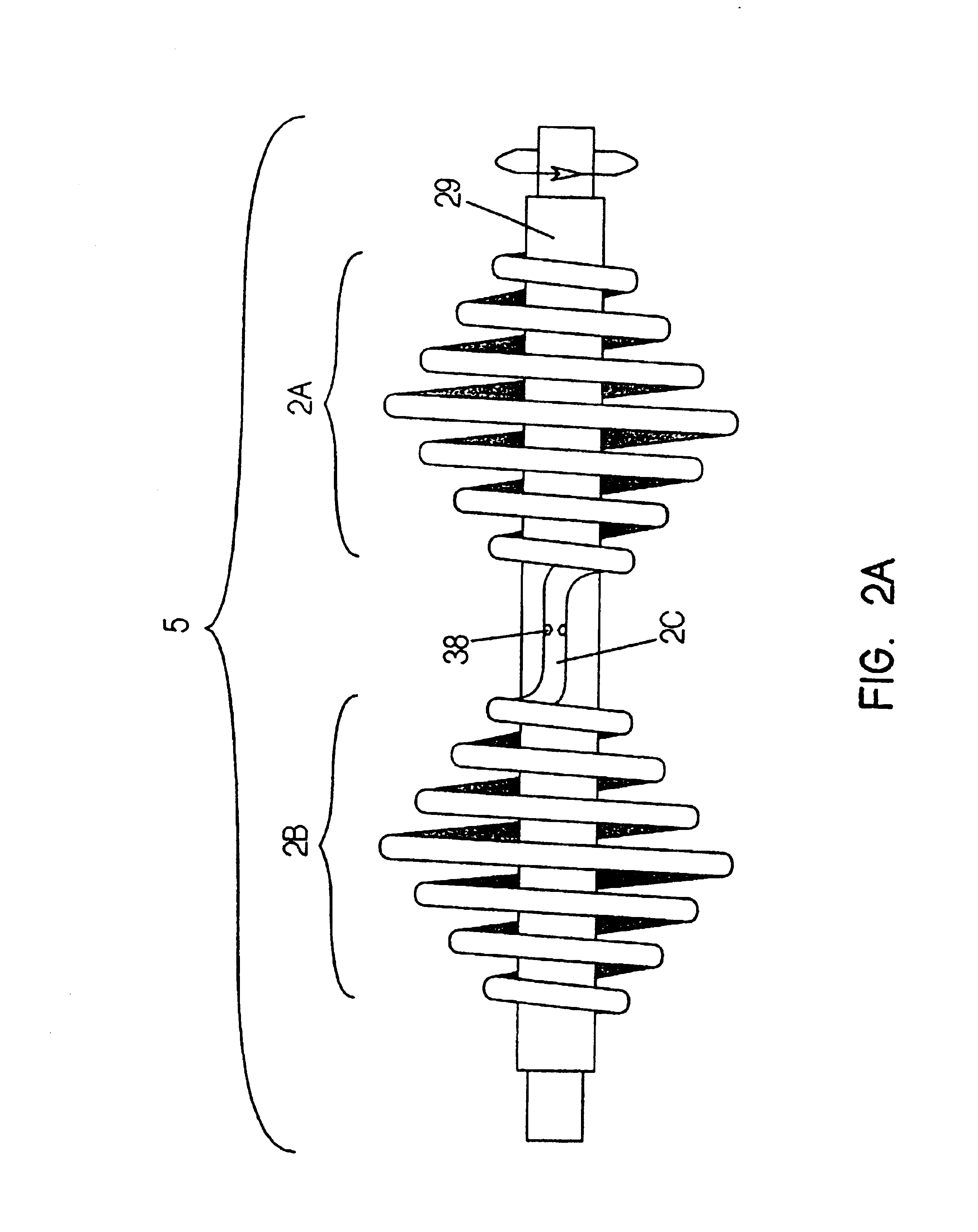
Centrifugal heat transfer engine and heat transfer systems embodying the same
a centrifugal heat transfer and heat transfer system technology, applied in the direction of indirect heat exchangers, lighting and heating apparatus, machine operation modes, etc., can solve the problems of inconvenient use, prone to fractionation of refrigerants, and general flammability of hydrocarbon based fluids containing hydrogen and carbon
- Summary
- Abstract
- Description
- Claims
- Application Information
AI Technical Summary
Benefits of technology
Problems solved by technology
Method used
Image
Examples
first embodiment
Applications of First Embodiment of Heat Transfer Engine hereof
[0203]In FIG. 13, the heat transfer engine of the first illustrative embodiment is shown installed on the roof of a building or similar structure, as part of an air handling system which is commonly known in the industry as a Roof-Top or Self-Contained air conditioning unit, or air handler. In this application, the heat transfer engine functions as a roof-top air conditioning unit which can be operated in its cooling mode or heating mode. The term “air conditioning” as used herein shall include the concept of cooling and / or heating of the air to be “temperature conditioned”, in addition to the conditioning of air for human occupancy which includes its temperature, humidity, quantity, and cleanliness. As shown, the air handling unit comprises an air supply duct 60 and an air return duct 61, both penetrating structural components of a building. The rotor of the centrifugal heat transfer engine is rotated by a variable-spee...
second embodiment
Applications of Second Embodiment of Heat Transfer Engine hereof
[0229]In FIG. 17, a heat transfer system according to the present invention is shown, wherein the rotor of the heat transfer engine thereof 70 is driven (i.e. torqued) by fluid flow streams 95A flowing through the secondary heat exchanging circuit 95B of the system. In this heat transfer system, heat liberated from the secondary heat exchanging portion 94 of the rotor is absorbed by a fluid 95A from pump 97A and a typical condenser cooling tower 97. As shown, cooling tower 97 is part of systematic fluid flow circuit in a cooling tower piping system where heat is exchanged with the cooling tower and consequently with the ambient atmosphere. As shown in FIG. 17, the heat transfer engine 70 is “pumping” a fluid 96A, such as water, through a typical closed-loop tube and shell heat exchanger 98 and its associated piping 96B and flow control valve 98A. This heat transfer system is ideal for use in chilled-water air conditioni...
PUM
 Abstract
Description
Claims
Application Information
 - R&D
- Intellectual Property
- Life Sciences
- Materials
- Tech Scout
- Unparalleled Data Quality
- Higher Quality Content
- 60% Fewer Hallucinations
Browse by: Latest US Patents, China's latest patents, Technical Efficacy Thesaurus, Application Domain, Technology Topic, Popular Technical Reports.
© 2025 PatSnap. All rights reserved.Legal|Privacy policy|Modern Slavery Act Transparency Statement|Sitemap|About US| Contact US: help@patsnap.com


