In-band group delay equalizer and distortion compensation amplifier
a group delay and amplifier technology, applied in waveguides, line-transmission details, baseband system details, etc., can solve the problems of increasing outer dimension and insertion loss, further increasing the peak of the group delay, and unable to achieve a flat characteristic in terms of the group delay over a wide band, so as to suppress the distortion to a very low level, suppress the distortion to a further lower level, and reduce the distortion
- Summary
- Abstract
- Description
- Claims
- Application Information
AI Technical Summary
Benefits of technology
Problems solved by technology
Method used
Image
Examples
first embodiment
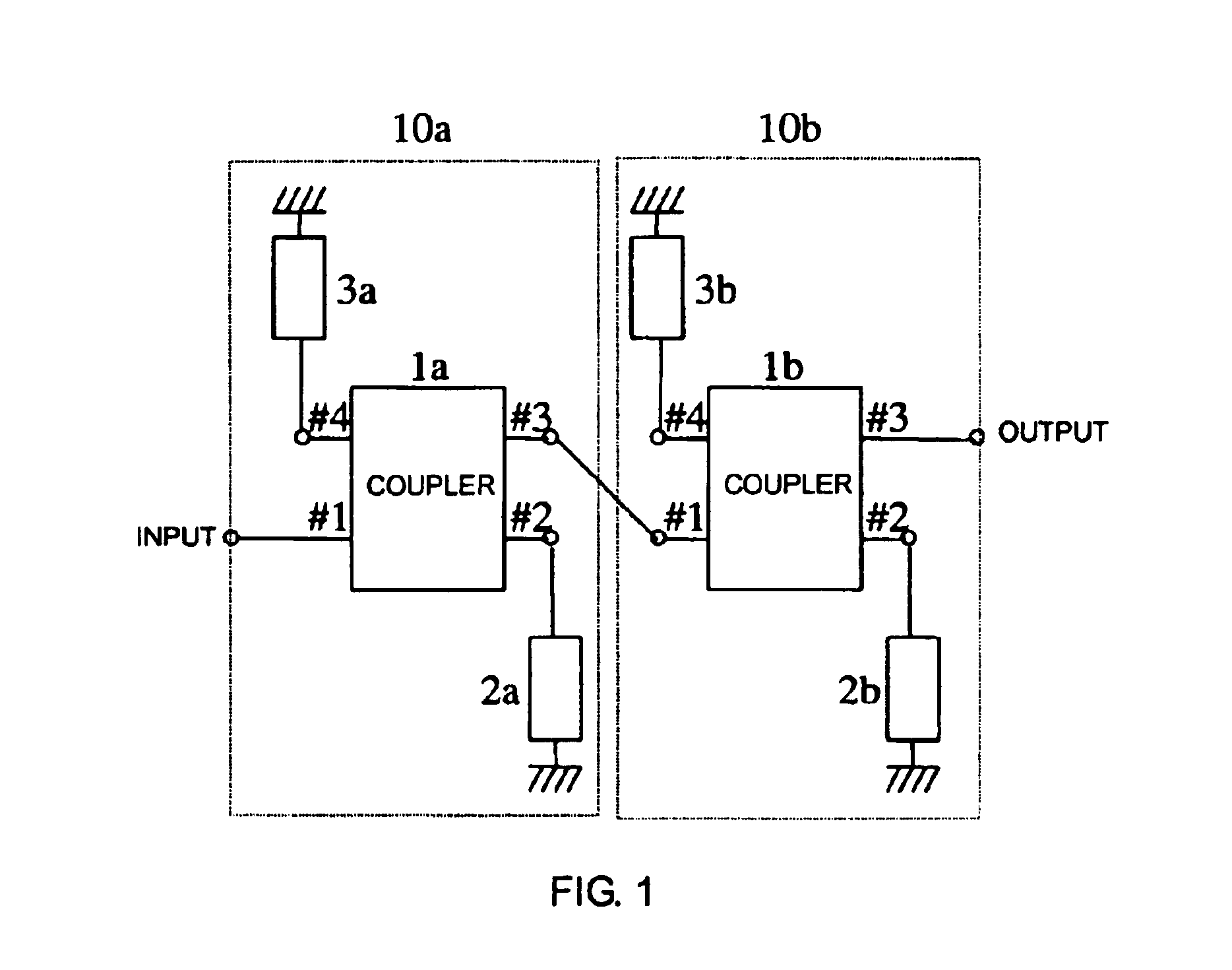
[0050]An in-band group delay equalizer (hereinafter, referred to simply as a “group delay equalizer”) is described below with reference to FIGS. 1 to 5.
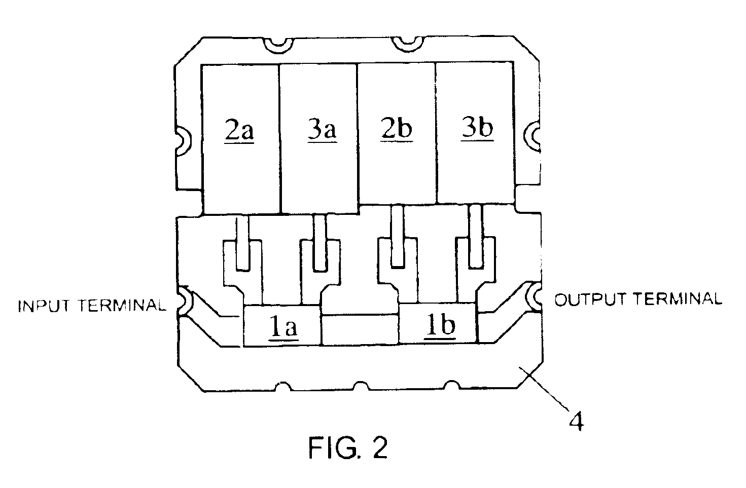
[0051]FIG. 1 is a circuit diagram of the group delay equalizer. The group delay equalizer includes a resonators 2a, 2b, 3a, and 3b, and 4-port hybrid couplers (hereinafter, referred to simply as couplers) 1a and 1b. Each of the couplers 1a and 1b includes a port #1 serving as an input port, ports #2 and #4 serving as divided output port, and a port #3 serving as a termination port. The divided output ports #2 are terminated with the resonators 2a and 2b, respectively, and the divided output ports #4 are terminated with the resonators 3a and 3b, respectively. The termination port #3 of each coupler is used as an output port.
[0052]Reference numeral 10a denotes a convex group delay circuit including a coupler 1a and two resonators 2a and 3a. A signal input via an input terminal is applied to the port #1 of the coupler 1a and output fro...
second embodiment
[0068]FIG. 6 shows an example of a hybrid coupler used in a group delay equalizer according to a
[0069]In the example shown in FIG. 6, the hybrid coupler is formed of a bridge circuit including inductors L1 and L2 and capacitors CO. Hybrid couplers using such a bridge circuit are employed, for example, as the couplers 1a and 1b shown in FIG. 1. That is, instead of the coupler having the structure shown in FIG. 3, a hybrid coupler using the bridge circuit may be employed. More specifically, two resonant circuits are connected to one such hybrid coupler using the bridge circuit thereby forming one convex group delay circuit. Two such convex group delay circuits are connected in cascade to form a group delay equalizer.
[0070]In FIG. 6, IN denotes an input terminal, and OUT denotes an output terminal. Circuit parameters are determined so that the phase difference between the input and output terminals becomes one quarter the wavelength at the operating frequency.
[0071]A signal applied to ...
third embodiment
[0077]A group delay equalizer is described below with reference to FIGS. 7 to 9B.
[0078]FIG. 7 is a circuit diagram thereof. In the example described earlier with reference to FIG. 1, a two-stage convex group delay circuit is used. In contrast, in this example shown in FIG. 7, three convex group delay circuits 10a, 10b, and 10c are used. More specifically, a port #3 of a coupler 1a, serving as the output port of the convex group delay circuit 10a, is connected to a port #1 of a coupler 1b, serving as the input port of the convex group delay circuit 10b, and a port #3 of the coupler 1b, serving as the output port of the convex group delay circuit 10b, is connected to a port #1 of a coupler 1c, serving as the input port of the convex group delay circuit 10c. A port #1 of the coupler 1a is used as the input port of the convex group delay circuit 10a, and a port #3 of the coupler 1c is used as the output port of the convex group delay circuit 10c.
[0079]Thus, the three convex group dela...
PUM
 Abstract
Description
Claims
Application Information
 - R&D
- Intellectual Property
- Life Sciences
- Materials
- Tech Scout
- Unparalleled Data Quality
- Higher Quality Content
- 60% Fewer Hallucinations
Browse by: Latest US Patents, China's latest patents, Technical Efficacy Thesaurus, Application Domain, Technology Topic, Popular Technical Reports.
© 2025 PatSnap. All rights reserved.Legal|Privacy policy|Modern Slavery Act Transparency Statement|Sitemap|About US| Contact US: help@patsnap.com


