
Diversity receiver with joint phase locked loop filter

a phase lock filter and receiver technology, applied in the field of diversity receivers, can solve the problems of bit errors, digital broadcast systems that can fail completely, and analog television signals degrade gracefully, so as to improve the overall bit error rate and increase the noise problem

Inactive Publication Date: 2005-08-30
AVAGO TECH INT SALES PTE LTD
View PDF5 Cites 19 Cited by
  • Summary
  • Abstract
  • Description
  • Claims
  • Application Information

AI Technical Summary

Benefits of technology

The present invention is a diversity antenna system for improving the reception of signals in a multiple channel receiver. The system uses identical antennas that are separated by several wavelengths, which provides improved reception by reducing interference. The system also uses joint processing of the signals from the two antennas, which allows for better signal quality and reduces noise. The invention also includes a shared timing loop filter for baud clock recovery, which ensures that both channels are synchronized. The technical effects of the invention include improved signal quality, reduced interference, and improved timing accuracy.

Problems solved by technology

While analog television signals degrade gracefully in the presence of interference, digital broadcast systems can fail completely when the bit error rate overcomes the error tolerance of the system.
Bit errors result from weak signals, noisy signals or signals subject to fading and distortion.
Furthermore, these obstructions reflect the transmitted signal such that multiple versions with varying amplitudes, phases and time delays are simultaneously received.
The indoor environment is even more complicated since there is rarely an unobstructed path between the transmitter and receiver antennas.
Furthermore, objects causing signal reflection and absorbtion are numerous and are often in motion.
Reception of the transmitted signal along multiple paths from the transmitter to the receiver causes signal distortion which manifests itself in a variety of ways.
The different paths have different delays that cause replicas of the same signal to arrive at different times (like an echo) and sum at the receiver antenna, causing inter-symbol interference.
The phases of these multipath signals may combine constructively or destructively resulting in large range of possible signal strengths.
Indoor signals typically have severe multi-path distortions and are changing rapidly in time, ranging from flat fades to deep in-band nulls to relatively unimpaired signals.
Conventional indoor TV antennas and outdoor antennas used with existing 8VSB receivers often do not produce reliable and uninterrupted reception of digital broadcast HDTV signals.

Method used


Image

  • Diversity receiver with joint phase locked loop filter
  • Diversity receiver with joint phase locked loop filter
  • Diversity receiver with joint phase locked loop filter

Examples


Embodiment Construction

System

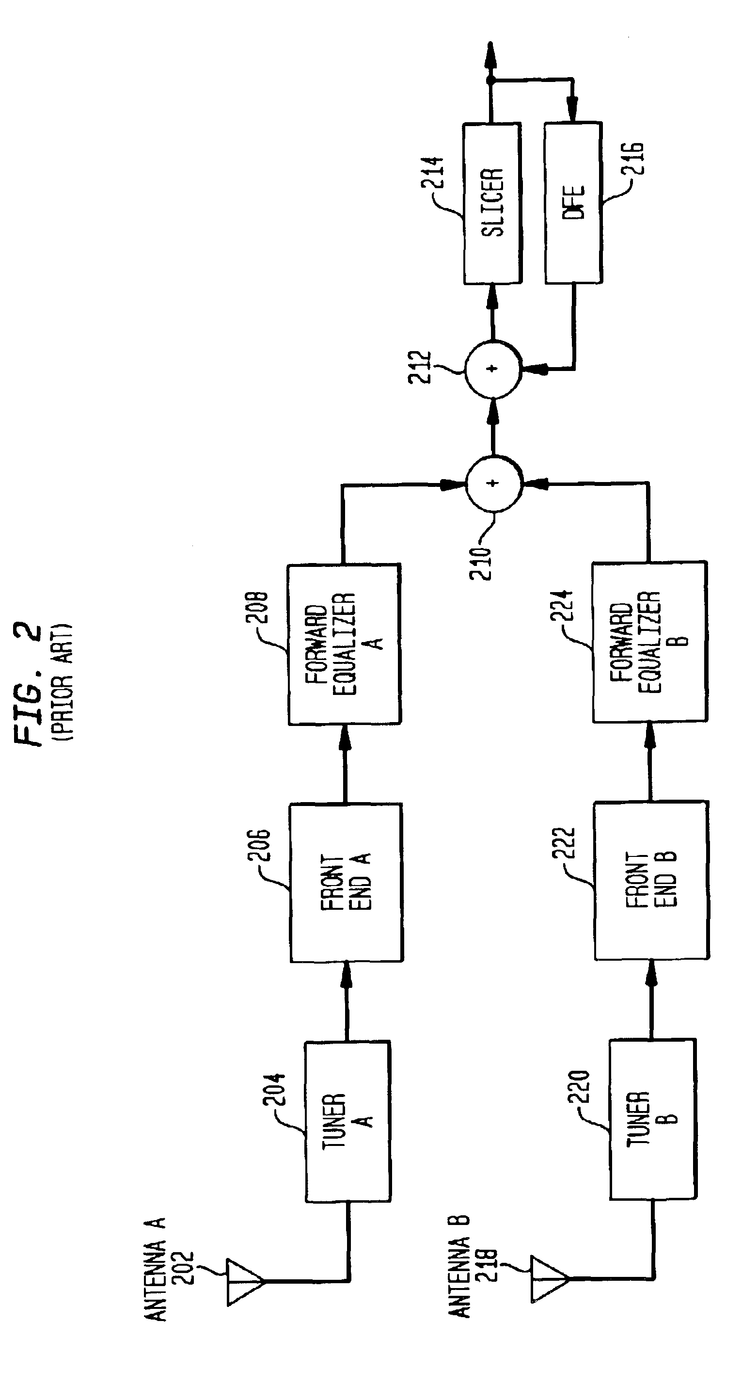
[0049]A prior art diversity receiver with two channels responsive to first and second antennas 202, 218 is shown in FIG. 2. The first channel includes a tuner 204, a front end signal processor 206 and a forward equalizer 208. The second channel includes a separate tuner 220, a separate front end signal processor 222 and a separate forward equalizer 224 each of which are independent of the corresponding functions in the first channel. The respective output of each of the two separate and independent channels of the diversity receiver are combined together in combiner 210, which combines the first and second channels of the diversity receiver into a single channel containing one combined signal. As indicated, there are numerous strategies in the prior art for combining the output signals from the channels of a multiple channel diversity receiver. The output of combiner 210 is coupled to a feedback equalization filter, comprising adder 212, slicer 214 and decision feedback equali...


PUM


Abstract

Original RF carriers are recovered for first and second channels in a diversity receiver and used to de-rotate (demodulate) each of the first and second received signals. The pilot loop filters of each channel are cross coupled to create a joint pilot loop between both channels. The channel with the stronger signal provides a dominant influence on the frequency of the synthesized recovered RF carrier in the channel with the weaker signal. The phase locked pilot loops in both channels will tend to be frequency locked to the frequency of the stronger signal, leaving the respective phase locked pilot loops to make an individual phase adjustment for each channel.

Description

[0001]“This is a divisional of application Ser. No. 09 / 363813, filed on Jul. 30, 1999.”, now U.S. Pat. No. 6,560,299.FIELD OF THE INVENTION[0002]The present invention relates to diversity receivers.BACKGROUND OF THE INVENTION[0003]Conventional television signals transmit video information in analog form by modulating the amplitude and frequency of a carrier signal. Digital television systems convert an analog video signal into digital information, which is transmitted by pulse modulating the amplitude and phase of a carrier signal. For example, in broadcasting high definition television (HDTV), digital information is transmitted by an 8 level amplitude modulation technique, known as 8VSB (vestigial sideband). In 8 VSB, modulation of a carrier to one of 8 levels (i.e., one of 8 symbols) defines 3 bits of digital information for each symbol clock interval. While analog television signals degrade gracefully in the presence of interference, digital broadcast systems can fail completely ...

Claims


Application Information

Patent Timeline
Patent Type & Authority Patents(United States)
IPC IPC(8): H04B7/08H04L27/00H04L27/06
CPCH04B7/0848H04L27/066H04L7/005H04L7/0029H04L2027/003H04L2027/0057
Inventor STROLLE, CHRISTOPHER HSHAH, ANAND MENDRES, THOMAS JHULYALKAR, SAMIR NSCHAFFER, TROY A
Owner AVAGO TECH INT SALES PTE LTD
Learn More