
Apparatus for and method of settling of mineral slurries

a technology for mineral slurries and settlers, which is applied in sedimentation settling tanks, liquid displacement, separation processes, etc., can solve problems such as premature shut-down of the settling apparatus for cleaning or repair, disruption of industrial processes, and delay, and achieve the effect of improving the design of gravity settling tanks

Inactive Publication Date: 2005-08-30
ALCAN INT LTD
View PDF17 Cites 28 Cited by
  • Summary
  • Abstract
  • Description
  • Claims
  • Application Information

AI Technical Summary

Benefits of technology

[0009]An object of the present invention, at least in a preferred form thereof, is to improve gravity settler design, particularly to accommodate slurries containing coarse particles.
[0010]Another object of the invention, at least in a preferred form thereof, is to provide a method of decanting mineral slurries containing both fine and coarse particles while minimizing problems caused by unwanted solid deposits.
[0011]Another object of the invention, at least in a preferred form thereof, is to provide a way of delaying or eliminating the formation of harmful solid deposits in settlers used for decanting mineral slurries.
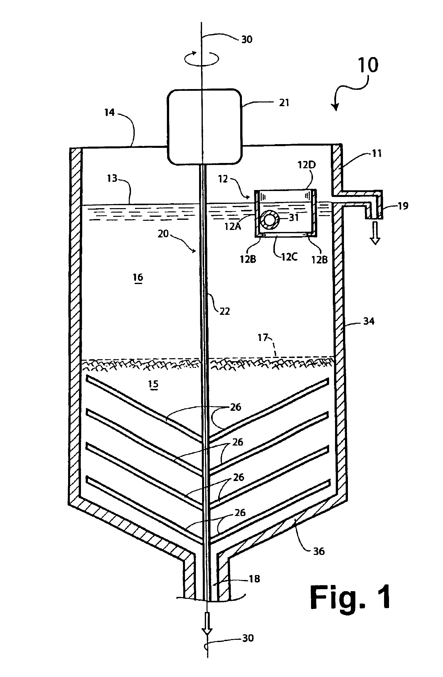
[0014]In the above method, the accumulation of solids from the fresh slurry immediately upstream of the opening in the slurry inlet means may be avoided by maintaining a suitably high rate of flow of fresh slurry throughout the entire slurry inlet means and the slurry opening to prevent settling of solids. In the apparatus, this can be achieved by ensuring that the slurry opening is the same size (area) as the cross-section of the slurry inlet means immediately upstream of the slurry opening, or is not significantly smaller.
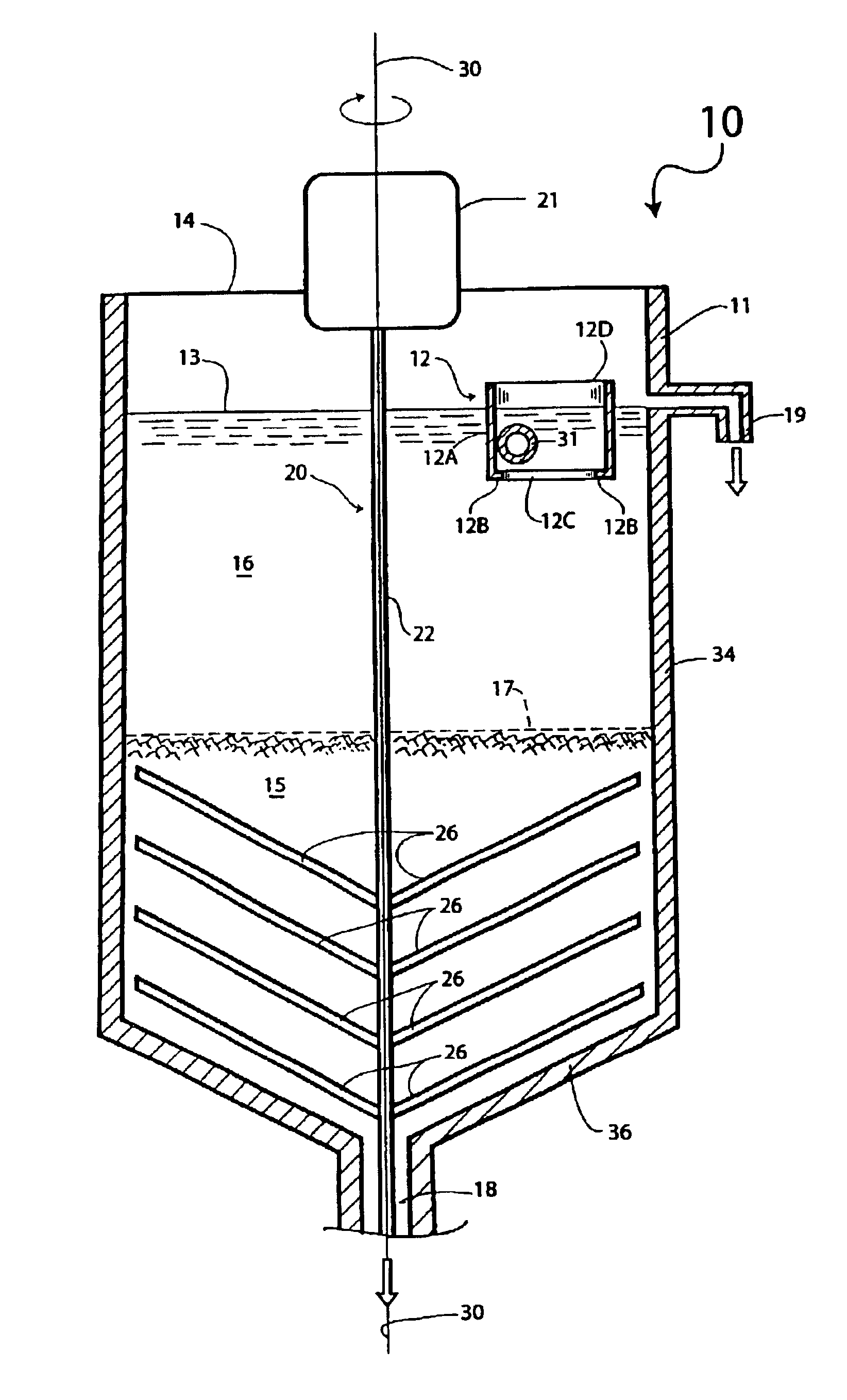
[0018]The slurry inlet means is preferably in the form of a vertically oriented feed well provided with a slurry opening at the bottom of the feed well creating a slurry flow into the body of slurry in the tank. The feed well has a cross-sectional area transversely of the slurry flow immediately upstream of the slurry opening, and ideally the slurry opening has a cross-sectional area that is at least 80% as large as the cross-sectional area of the feed well immediately upstream of the slurry opening. This avoids or prevents substantial accumulation of solids from the fresh slurry in the feed well immediately upstream of the slurry opening as the fresh slurry does not become unduly quiescent within the feed well. Other forms of slurry inlet means may be employed, including a simple inlet pipe terminating in a delivery hole for introducing fresh slurry into the tank. In general, the slurry inlet means are preferably of such a design that a generally cylindrical column or “plume” of fresh flocculating slurry is introduced into the slurry body in the tank.

Problems solved by technology

However, it has been found that when slurries contain coarse particles, in addition to fine particles, problems can arise.
Such deposits may eventually cause blockages and / or cause the stirrer to stop or may even damage the stirrer due to the application of excessive torque, and this requires a premature shut-down of the apparatus for cleaning or repair.
Obviously, this causes disruption of the industrial process and delay.

Method used


Image

  • Apparatus for and method of settling of mineral slurries
  • Apparatus for and method of settling of mineral slurries
  • Apparatus for and method of settling of mineral slurries

Examples


example 1

[0048]All test conditions of this Example were similar to those of Comparative Example 1 above except that the feed well was located at half the radius measured from the center of the tank to the wall.

[0049]The feed solids contained 15% (w / w) coarse particles measured on a dry basis.

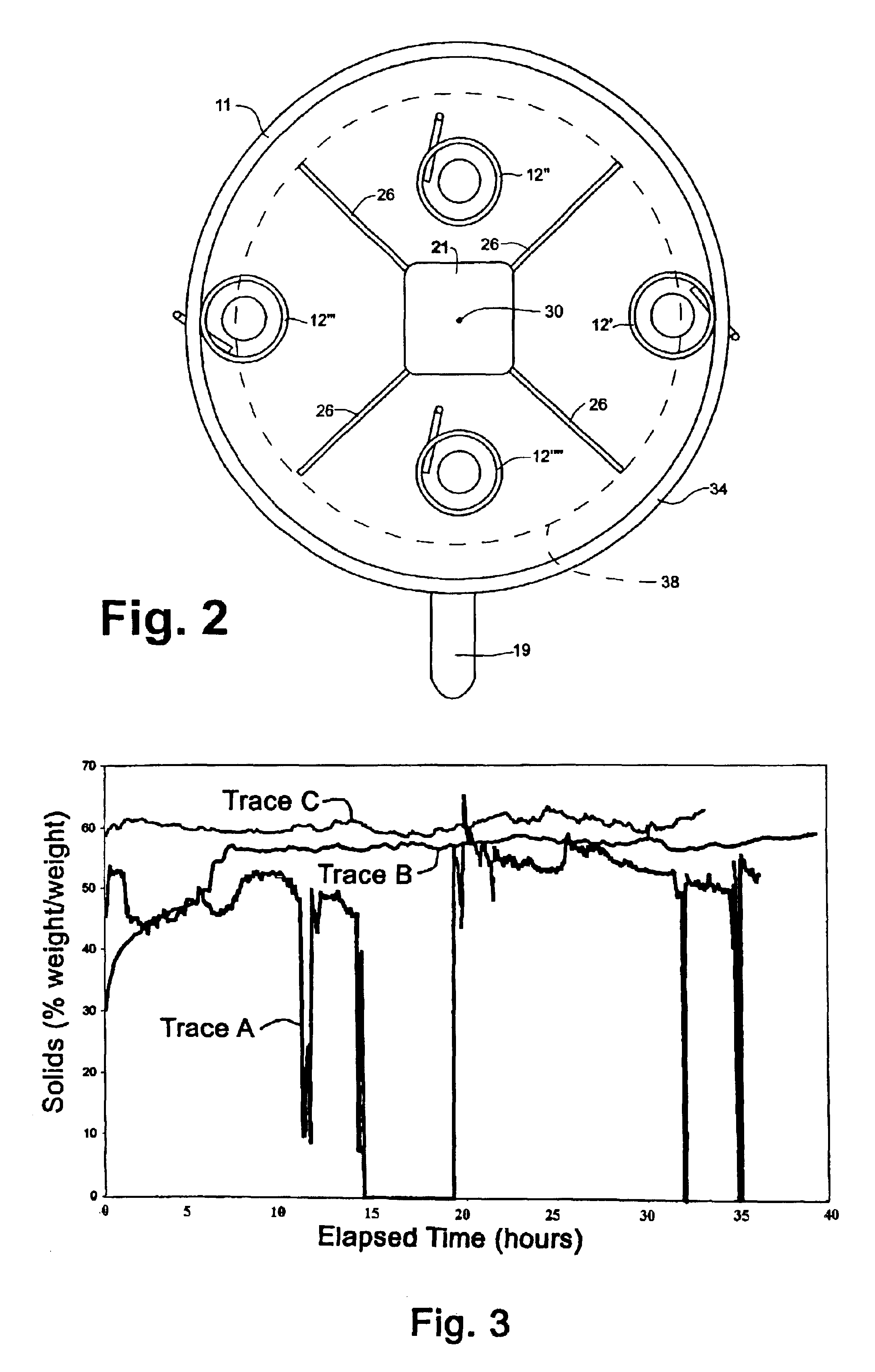
[0050]The results obtained with that set-up gave an underflow solids concentration of 55% and downtime of the unit of the order of 0%. The graph of FIG. 3 (trace B) gives the variation of the percentage of solids with time. The evolution of underflow solids is clearly quite even and regular.

example 2

[0051]All the test conditions of this Example are similar to those of Comparative Example 1 above except that the feed well was again located at half the radius measured from the center of the tank to the wall.

[0052]The feed solids contained 27% (w / w) coarse particles measured on a dry basis.

[0053]The results obtained with this arrangement provided a solids concentration of 60% and downtime of the unit of the order of 0%. The graph of FIG. 3 (trace C) shows the variation of the percentage of solids with time. The evolution of underflow solids is clearly quite even and regular.


PUM

PropertyMeasurementUnit
Fractionaaaaaaaaaa
Fractionaaaaaaaaaa
Fractionaaaaaaaaaa

Abstract

The invention relates to a settler for decanting mineral slurries and a method thereof. The settler comprises a tank for holding and decanting a body of slurry to form a thickened slurry as a lower layer and a clarified liquid as an upper layer, the tank having a side wall, a bottom and a top, an outlet for the thickened slurry at the bottom of the tank, an outlet for the clarified liquid layer near the top of the tank, a slurry inlet means near the top of the tank for introducing fresh slurry into the tank, the slurry inlet means having a slurry opening through which fresh slurry joins the body of slurry in the tank, and a stirrer having a generally vertical axis around which the stirrer rotates or reciprocates. The slurry opening is displaced laterally relative to the generally vertical axis of the stirrer and the slurry inlet means is configured to allow the fresh slurry to enter the slurry body without accumulating solids from the fresh slurry at the slurry opening.

Description

CROSS-REFERENCE TO RELATED APPLICATION[0001]This application claims the priority right of prior U.S. patent application Ser. No. 60 / 345,867 filed on Nov. 9, 2001 by applicants herein.BACKGROUND OF THE INVENTION[0002]1. Field of the Invention[0003]This invention relates to settlers for mineral slurries (sometimes referred to as gravity settlers, pressure settlers, clarifiers, separators, thickeners, deep thickeners, and the like) used in industrial processes. More particularly, the invention relates to settlers used for decanting or thickening slurries of minerals or mineral tailings, for example red mud produced during the extraction of alumina from bauxite by the Bayer alkaline digestion process.[0004]2. Background Art[0005]Many industrial processes make use of tanks or reservoirs in which slurries of mineral materials or tailings are allowed to settle and densify, often with the assistance of flocculants or other chemical aids, to produce a thickened lower slurry layer and a clari...

Claims


Application Information

Patent Timeline
IPC IPC(8): B01D21/00B01D21/02B01D21/01B01D21/06
CPCB01D21/0018B01D21/0027B01D21/0039B01D21/01B01D21/02B01D21/08B01D21/2416B01D21/2427B01D21/30B01D21/2405B01D21/06B01D21/245B01D2221/04
Inventor PELOQUIN, GUYSIMARD, GUYBOIVIN, ALAINDUFOUR, RENALDLEMYRE, ROCKCARRUTHERS, ANDREW
Owner ALCAN INT LTD
Learn More