
Objective lens for use in optical pickup apparatus and optical pickup apparatus

a technology for optical pickups and objective lenses, applied in the direction of lenses, instruments, record information storage, etc., can solve the problems of high numerical aperture of objective lenses, high cost of plastic-molded single lenses produced by using high technology, and higher technical difficulty in metal mold manufacturing and molding

Inactive Publication Date: 2005-07-19
KONICA CORP
View PDF8 Cites 7 Cited by
  • Summary
  • Abstract
  • Description
  • Claims
  • Application Information

AI Technical Summary

Benefits of technology

[0046]When the plastic-molded single lens is used, for the request of a higher aperture number of the objective lens for the optical pick-up, a curvature of an optical surface becomes greater, lens performance is more affected by the shifts of both optical surfaces, production of the metal mold for molding work and assembling accuracy become very severe, and maintenance of the product quality becomes very severe, which is a problem. However, the structure mentioned above eliminates the problem, and makes it possible to mold individually a plurality of the plastic-molded lenses each having a relatively small aperture and to combine them and obtain the plastic-molded lenses which can answer the requirement of the higher numerical aperture. Due to this, the productivity of the metal mold is so excellent that the lens performance can be transferred from the metal mold precisely, and the high performance lens can be easily produced. Further, since at least two plastic-molded lenses are made to be in contact with each other, or one of those lenses is held by the other lens, to constitute the objective lens for the optical pick-up, the higher precision and the high performance are easily realized, and it is easy to answer the requirement for the higher numerical aperture or the miniaturization of the objective lens for the optical pick-up, compared with an occasion where each lens is positioned and fixed respectively on the lens barrel. Further, it is easy to constitute so that aberration and errors such as astigmatism owned by each lens can correct each other, because the invention uses a plurality of the plastic-molded lenses.
[0079]In the invention described in Structure (3-13), coefficient of water absorption of the hardened adhesive agent applied on almost all circumference of the fitting section is 0.1%-10%, and vapor generated in the clearance between optical functional surfaces of the optical elements is absorbed in the adhesive agents, thus, it is possible to prevent that vapor generated in the clearance between optical functional surfaces of the optical elements is condensed into a dewdrop.

Problems solved by technology

However, there is a problem that the attainment of the high numerical aperture of the objective lens for the optical pick-up by using the plastic-molded single lens is very difficult, because the lens performance is affected greatly by shifts of both optical surfaces, further, when using short wavelength light, such as blue purple laser having the wave length of about 400 nm for the light source, the influence is greater remarkably, resulting in a higher technical difficulty in metal mold manufacturing and molding.
Further, there is a problem that the plastic-molded single lens finally produced by using the high technology is expensive necessarily.
For example, when an objective lens for an optical disk has a space, a deterioration of a surface accuracy of the effective optical surface and condensation mentioned above cannot be ignored, resulting in a problem.
In this optical unit, a clearance surrounded by a first optical element and a second optical element is made airtight, and when this clearance is made airtight, if ambient temperature and humidity for the optical unit are changed, air representing a gas existing in the clearance is expanded or compressed, and thereby, external pressure is applied on the first optical element and the second optical element, resulting in occurrence of deterioration of surface accuracy of an optical functional surface, and when ambient temperature used is lowered, moisture contained in the clearance turns out to be in the state of saturation, resulting in dew condensation which affects optical power.
For example, when there is a clearance in an objective lens for optical disc, a fall of surface accuracy on an optical functional surface and dew condensation have been problems which cannot be ignored.
Namely, it is a problem that a change of ambient temperature makes moisture in a clearance between optical elements to be condensed into a dewdrop which sticks to the surface of an optical functional surface, and when this dew condensation is caused, optical function cannot be attained.

Method used


Image

  • Objective lens for use in optical pickup apparatus and optical pickup apparatus
  • Objective lens for use in optical pickup apparatus and optical pickup apparatus
  • Objective lens for use in optical pickup apparatus and optical pickup apparatus

Examples


Embodiment Construction

[0104]Referring to the drawings, the embodiments of the objective lens for the optical pick-up and the optical pick-up employing the objective lens for the optical pick-up of the invention to achieve the first object are explained as follows.

[0105](The Embodiment of 1—1)

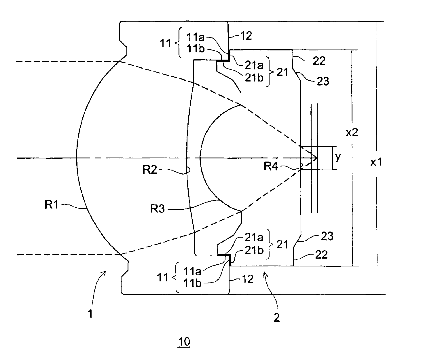
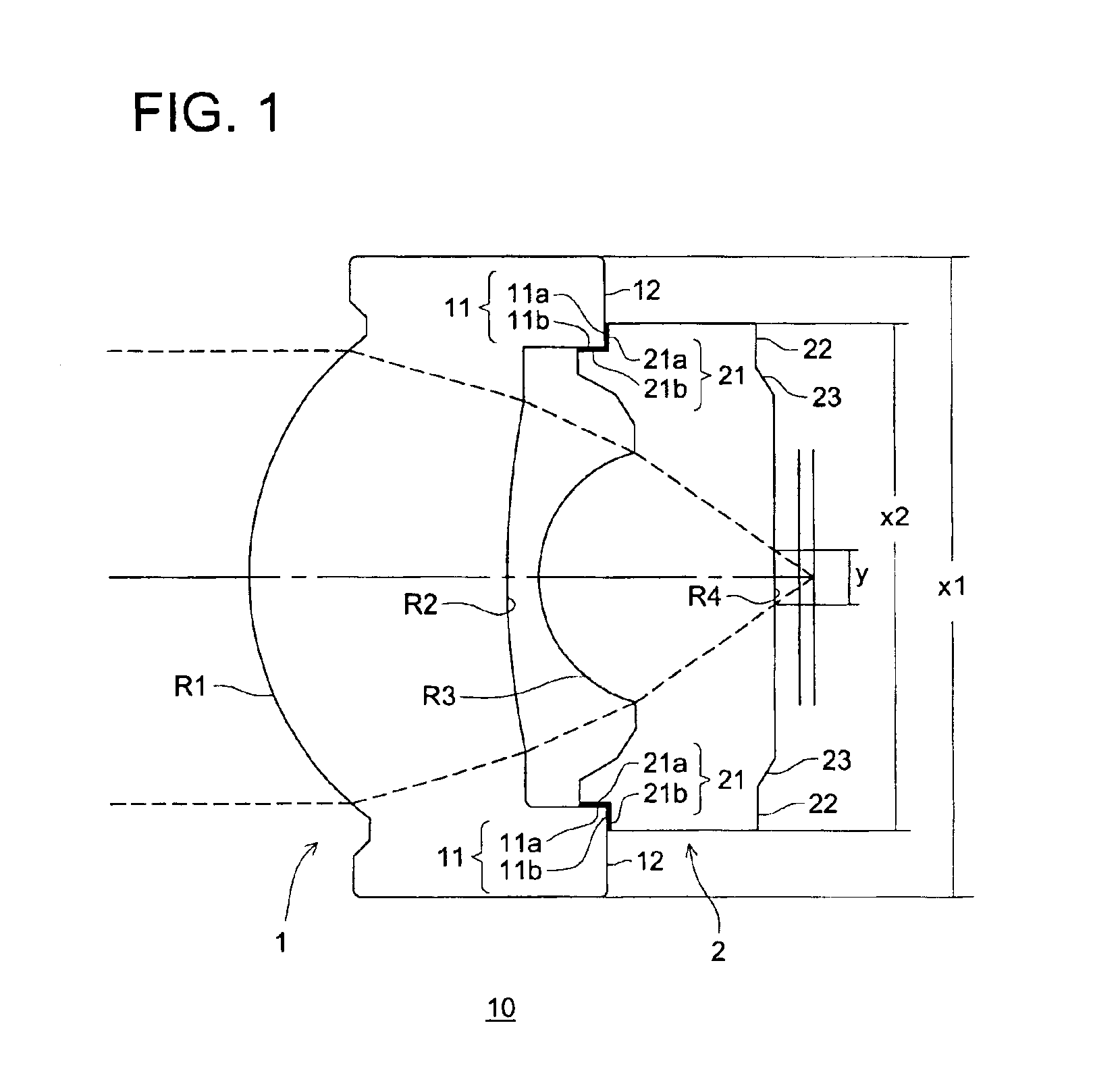
[0106]FIG. 1 is a sectional view of an objective lens for an optical pick-up, and FIG. 2 is a schematic structural drawing of an optical pick-up wherein the objective lens for the optical pick-up shown in FIG. 1 is incorporated. An example of the objective lens which is structured by two plastic-molded lenses is shown in this embodiment.

[0107]In FIG. 1, objective lens 10 for an optical pick-up is composed of object side lens 1 arranged at a light source side of the optical pick-up, and image side lens 2 arranged at the opposite side of the light source of the optical pick-up, which faces an optical information recording medium, when recording information on the optical information recording medium such as the optical...


PUM

PropertyMeasurementUnit
coefficient of water absorptionaaaaaaaaaa
wave lengthaaaaaaaaaa

Abstract

An objective lens for use in an optical pickup apparatus, comprises a first lens molded with a plastic and having an optically functional section, flange section provided around the periphery of the optically functional section, and a first contacting section provided on the flange section; and a second lens molded with a plastic, located opposite to the first lens and having an optically functional section, a flange section provided around the periphery of the optically functional section, and a second contacting section provided on the flange section. The first lens and the second lens are joined in such a way that the first contacting section and the second contacting section are brought in contact with each other.

Description

[0001]This application is a continuation-in-part application of U.S. patent application Ser. No. 10 / 050,560, filed on Jan. 18, 2002, now abandoned.BACKGROUND OF THE INVENTION[0002]The present invention relates to an optical pick-up objective lens which is used for an optical pick-up that performs information recording or reproduction for an optical information recording medium representing an optical disk, and to an optical pick-up wherein the optical pick-up objective lens is used.[0003]In particular, the present invention relates to an optical unit and an optical apparatus, and in more particular, to an optical unit in which a first optical element and a second optical element are unitized in one body and to an optical apparatus having this optical unit.[0004]In the past, a plastic-molded single lens has been used mainly for an optical pick-up objective lens. A large number of the plastic-molded single lenses are used for an optical pick-up for recording or reproduction for not on...

Claims


Application Information

Patent Timeline
Patent Type & Authority Patents(United States)
IPC IPC(8): G02B3/02G02B7/02G11B7/00
CPCG02B7/022G11B7/1374G11B2007/13727
Inventor WADA, KAZUHIROHATTORI, HIROYUKIEGURO, YAYOLARAI, NORIKAZUHONDA, KOJIHONDA, YUICHIATARASHI, YUICHI
Owner KONICA CORP
Learn More