
Single tube densitometer

a single tube, densitometer technology, applied in instruments, borehole/well accessories, surveys, etc., can solve the problems of large inaccuracy of density measurement, poor work efficiency in measuring flow of highly viscous fluid, and high cost of components, so as to improve the accuracy and reliability of measurement devices.

Inactive Publication Date: 2005-07-05
HALLIBURTON ENERGY SERVICES INC
View PDF27 Cites 73 Cited by
  • Summary
  • Abstract
  • Description
  • Claims
  • Application Information

AI Technical Summary

Benefits of technology

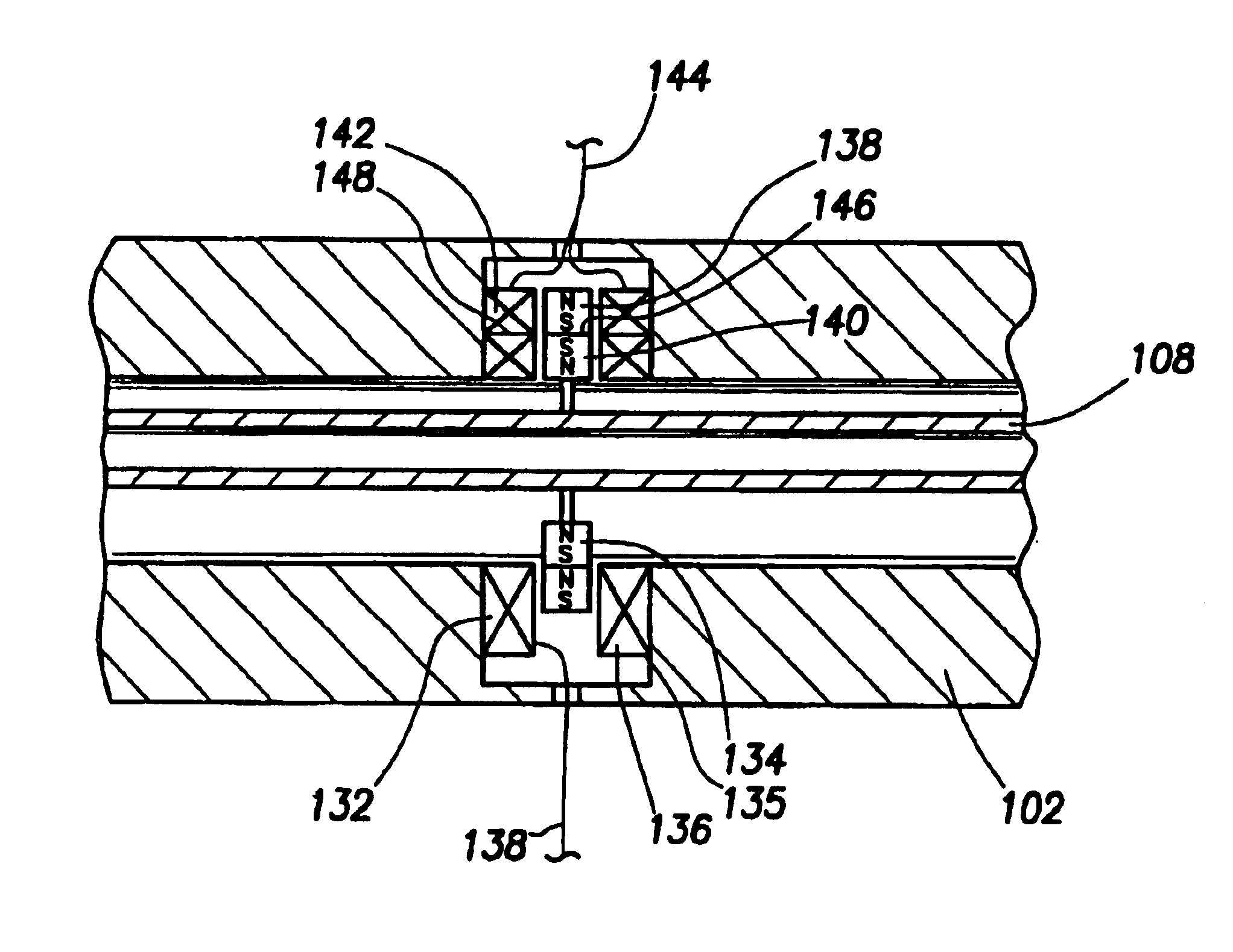
[0012]Accordingly, there is disclosed herein a measurement device for determining fluid properties from vibration amplitudes of a sample cavity. In one embodiment, the measurement device includes a sample flow tube, a vibration source, a vibration detector, and a measurement module. The vibration source and vibration detector are arranged in such a manner to minimize any interference in the measured signal. The sample flow tube receives a flow of sample fluid for characterization. The measurement module employs the vibration source to generate vibrations in the tube. The measurement module analyzes the measured signal from the vibration detector on the tube to determine properties of the sample fluid, such as density, viscosity, compressibility, water fraction, and bubble size. The measurement module may further detect certain flow patterns such as slug flow, for example.
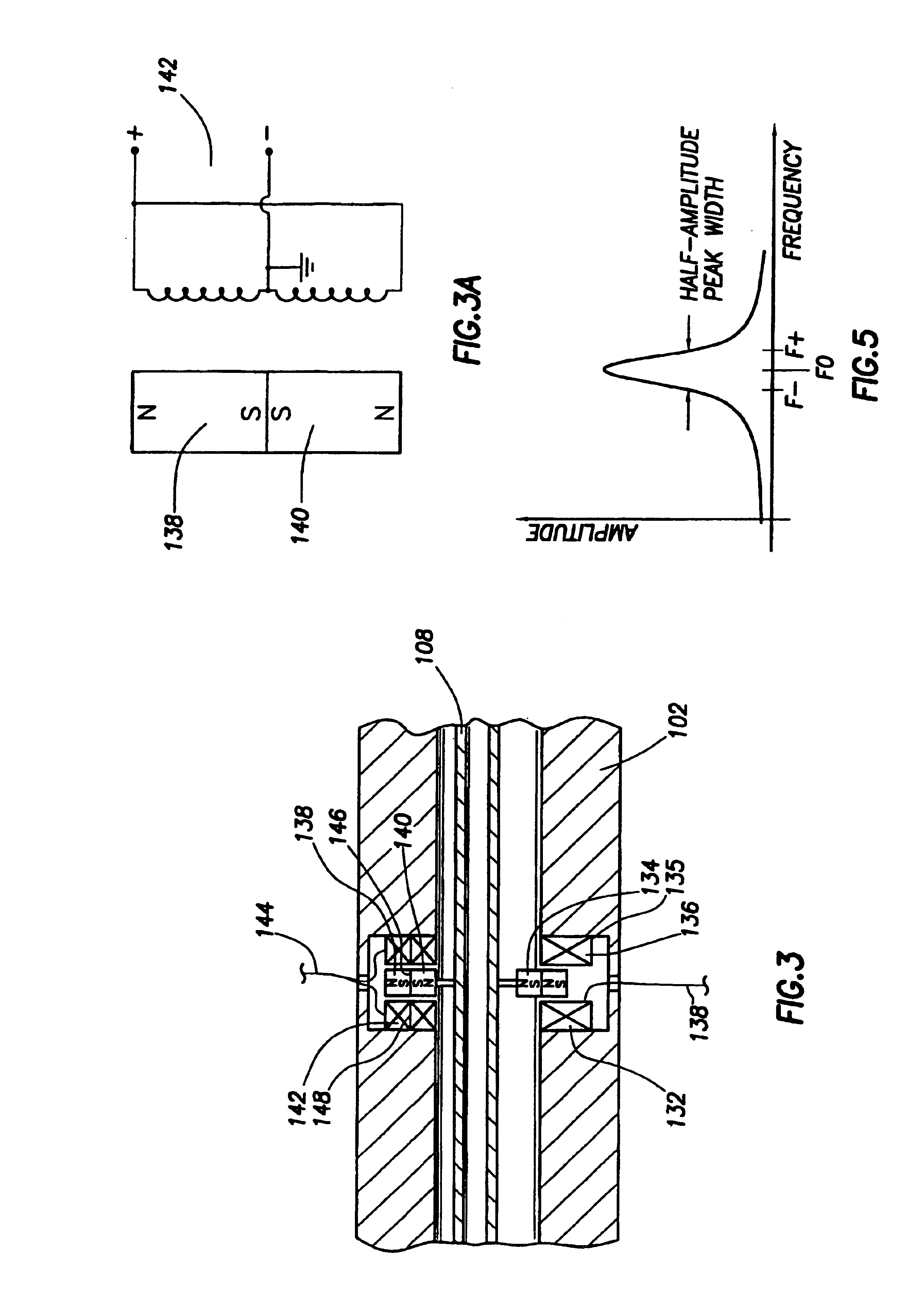
[0013]To determine the sample fluid density, the measurement module identifies the resonance frequency of the sample flow tube. The density can then be calculated according to a formula that compensates for the temperature and pressure response of the system. The measurement device has preferably calibrated so that the device can compensate for varying temperature and pressure in the wellbore. Other fluid properties may also be determined from the sample tube's resonance peak amplitude, peak width and / or peak shape. Variation of the density measurements may be used to detect and characterize multiple phase fluid flow. The use of the present invention is expected to greatly enhance the accuracy and reliability of the measurement device over a range of temperatures, pressures, and shock accelerations such as those that may be found in a borehole.

Problems solved by technology

Given the large quantities of crude oil that are usually involved, any small inaccuracies in measuring density can disadvantageously accumulate over a relatively short interval of time to become a large error in a totalized volumetric measure.
These types of mass flowmeters, while they function excellently in the mass flow measurement of low viscosity fluids, work poorly in measuring flows of highly viscous fluids because the fluid's viscosity introduces error in the data acquisition for the mass flow rate.
While the circuit taught in Reusch may provide accurate density measurements, it unfortunately possesses several drawbacks.
Such components are quite expensive.
Second, the analog circuit disclosed in this patent cannot be independently calibrated to compensate for changing characteristics of the electronic components—such as offset, drift, aging and the like.
Unfortunately, after the circuit has been calibrated in this fashion, component characteristics will subsequently change over time and thereby inject errors into the density readings produced by the circuit.
Because of the limited envelope available in downhole applications, the transmitter is often located in close proximity to the receiver.
This close proximity between the transmitter and receiver is thought to cause interference between the two components, which is likely a result of the interaction between the magnetic fields of the components.
This is of particular concern with the receiver because any interference may distort the signal and cause difficulty in accurately recognizing the vibratory response of the flow tube.

Method used


Image

  • Single tube densitometer
  • Single tube densitometer
  • Single tube densitometer

Examples


Embodiment Construction

Apparatus / Tube / Sensors

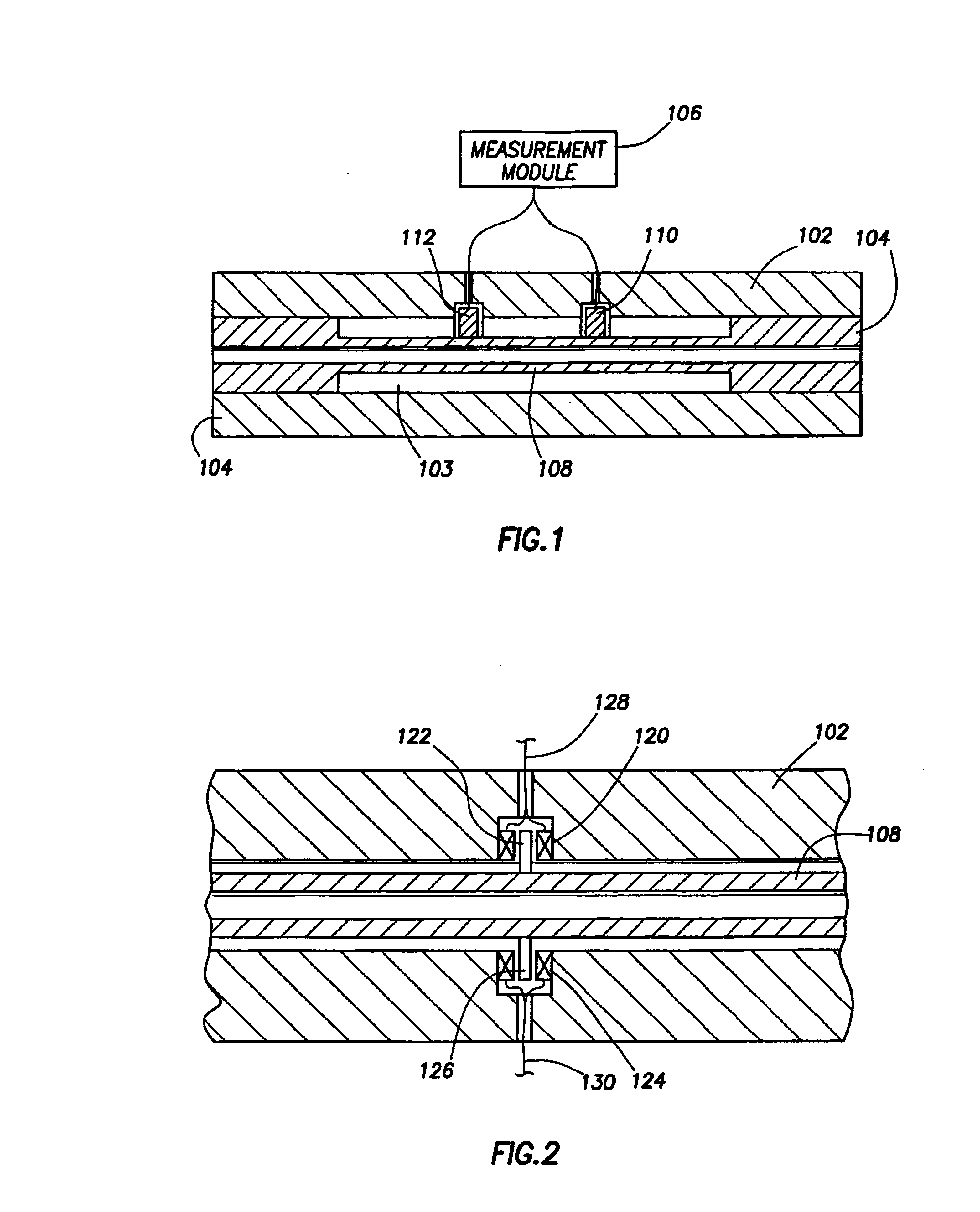
[0025]Referring now to FIG. 1, one embodiment of a device for measuring density and viscosity of a flowing fluid generally includes a rigid housing 102, two bulkheads 104, a single flow tube 108, a single vibration source 110, a single vibration detector 112, and a measurement module 106. The rigid housing 102 surrounds and protects a volume 103 through which the flow tube 108 passes and reduces the response to vibrations not associated with particular vibratory modes of the flow tube 108. The bulkheads 104 seal the volume and secure the flow tube 108 within that volume. The volume 103 preferably contains air, a vacuum or a relatively inert gas such as nitrogen or argon. If gasses are used, then they are preferably at atmospheric pressure when the device is at room temperature.

[0026]The rigid housing 102, bulkheads 104, and flow tube 108 are preferably made from material in a configuration that can withstand pressures of more than 20,000 psi (pounds per square ...


PUM

PropertyMeasurementUnit
temperaturesaaaaaaaaaa
pressuresaaaaaaaaaa
specific gravityaaaaaaaaaa

Abstract

A measurement device is provided that determines fluid properties from vibration frequencies of a sample cavity. In one embodiment, the measurement device includes a sample flow tube, vibration source and detector mounted on the tube, and a measurement module. The sample flow tube receives a flow of sample fluid for characterization. The measurement module employs the vibration sources to generate vibrations in the tube. The measurement module combines the signals from the vibration detector on the tube to determine properties of the sample fluid, such as density, viscosity, compressibility, water fraction, and bubble size. The measurement module may further detect certain flow patterns such as slug flow, for example. To measure the sample fluid density, the measurement module determines the resonant frequency of the sample flow tube. The density can then be calculated according to a formula that compensates for the temperature and pressure of the system.

Description

CROSS-REFERENCE TO RELATED APPLICATIONS[0001]This is a divisional application of U.S. patent application Ser. No. 10 / 055,202, filed Oct. 29, 2001 now U.S. Pat. No. 6,688,176, issued Feb. 10, 2004 and entitled “Single Tube Densitometer”, which is a continuation-in-part application of U.S. patent application Ser. No. 09 / 482,783 filed Jan. 13, 2000 now U.S. Pat. No. 6,378,364, issued Apr. 30, 2002 and entitled “Downhole Densitometer.” Such patents are hereby incorporated herein by reference.BACKGROUND OF THE INVENTION[0002]The present invention relates generally to devices and methods for measuring fluid density and other fluid flow properties in a flow stream, where fluid is taken to mean any liquid, gas, or mixture thereof, including those which contain solids. More particularly, the present invention relates to a high-accuracy density and viscosity measurement device suitable for use in a high-temperature, high-pressure, high-shock environment such as may be encountered in a wellbor...

Claims


Application Information

Patent Timeline
Patent Type & Authority Patents(United States)
IPC IPC(8): E21B47/10E21B49/08E21B49/00E21B47/06G01F1/84G01N11/10G01F1/76G01N11/16G01N9/00G01H11/00G01H11/02G01N9/18
CPCG01F1/8495G01H11/02G01N9/002G01N11/167E21B47/06G01F1/849E21B49/08G01F1/8409G01F1/8413G01F1/8436E21B47/101G01N2009/006E21B2049/085E21B47/107E21B49/0875
Inventor STORM, JR., BRUCE H.MASINO, JAMESPROETT, MARK A.PELLETIER, MICHAEL T.
Owner HALLIBURTON ENERGY SERVICES INC
Learn More