
Digitally controlled impedance driver matching for wide voltage swings at input/output node and having programmable step size

a technology of wide voltage swing and driver, applied in the direction of pulse technique, oscillation generator, reliability increasing modifications, etc., can solve the problems of increasing layout area and routing traffic, reducing the impedance of each fine finger, and inaccurate output impedance of dci driver

Inactive Publication Date: 2005-06-21
SEMICON COMPONENTS IND LLC
View PDF10 Cites 32 Cited by
  • Summary
  • Abstract
  • Description
  • Claims
  • Application Information

AI Technical Summary

Benefits of technology

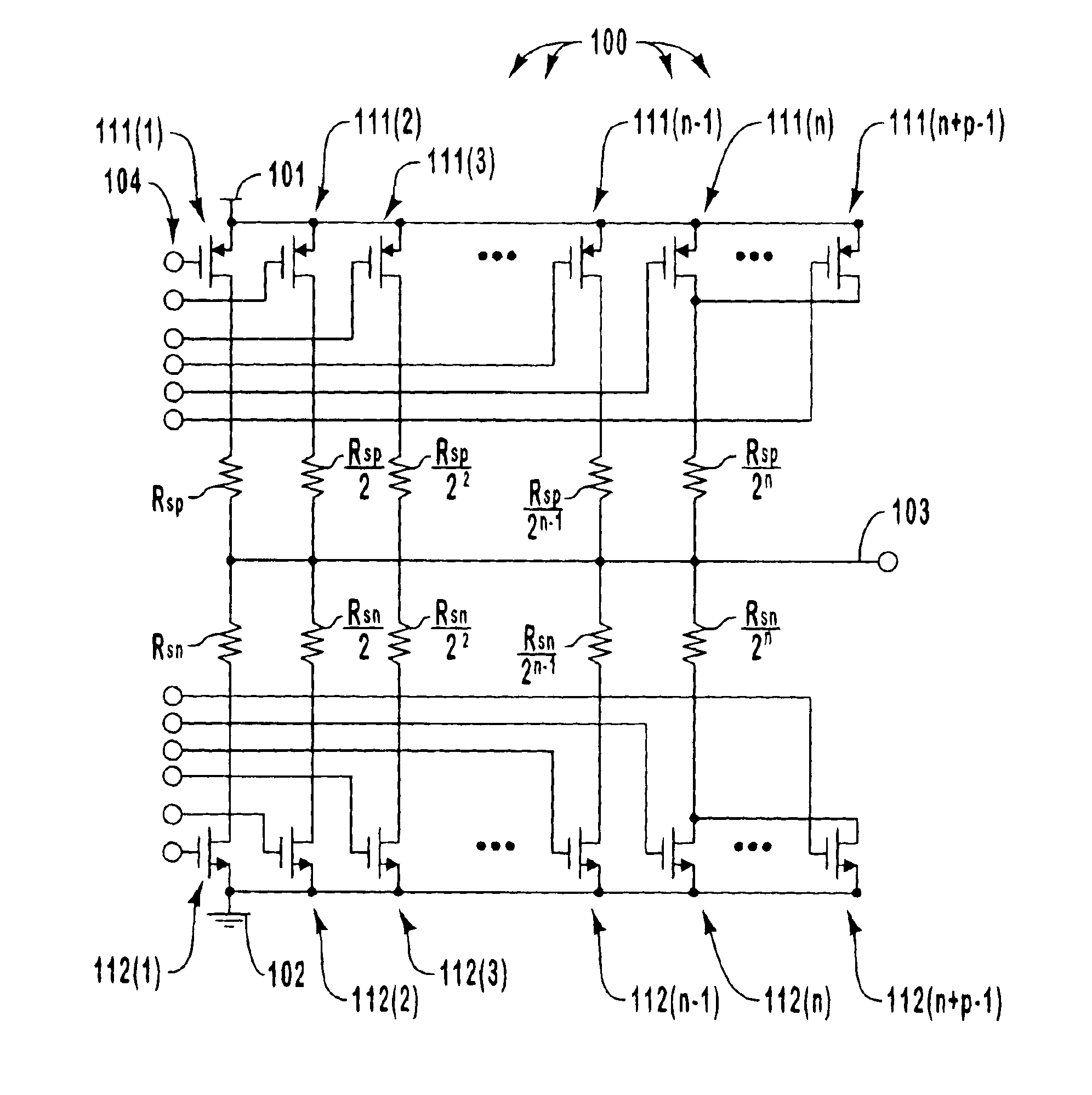
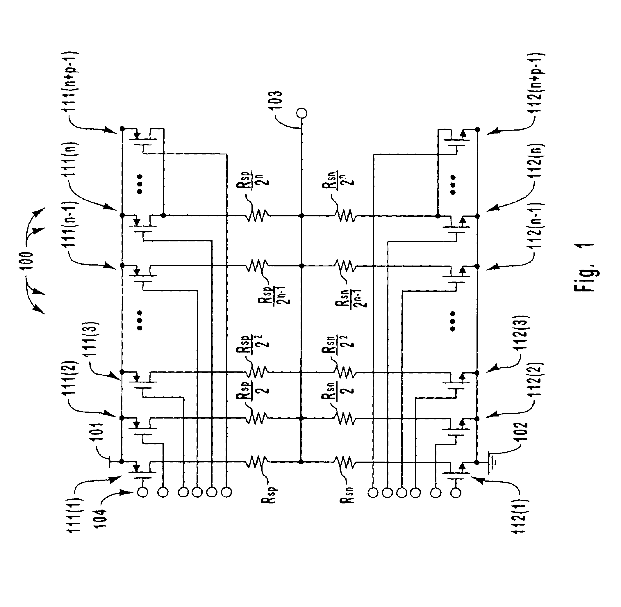
[0016]Some of the fingers are sized in binary ratio or some other differential configuration. In other words, the ideal effective length-to-width ratio based on the mask dimensions of a FET in one finger differs from the ideal effective length-to-width ratio of the FET in another finger. This would cause the actual effective length-to-width ratio to vary significantly from one FET in one finger to another FET in another finger. In binary configuration, the length-to-width ratios of the FETs are sized in approximate binary ratio. Whatever the ratio of the differential configuration, the associated series resistors are also appropriately sized according to the ratio of the differential configuration. Accordingly, the total impedance contribution of one finger is in proper proportion to the total impedance contribution from the other fingers, even if those impedances are not equal. Other of the FETs having the lowest length-to-width ratio are sized approximately equally to each other. These FETs may share the same resistor to thereby conserve layout area.
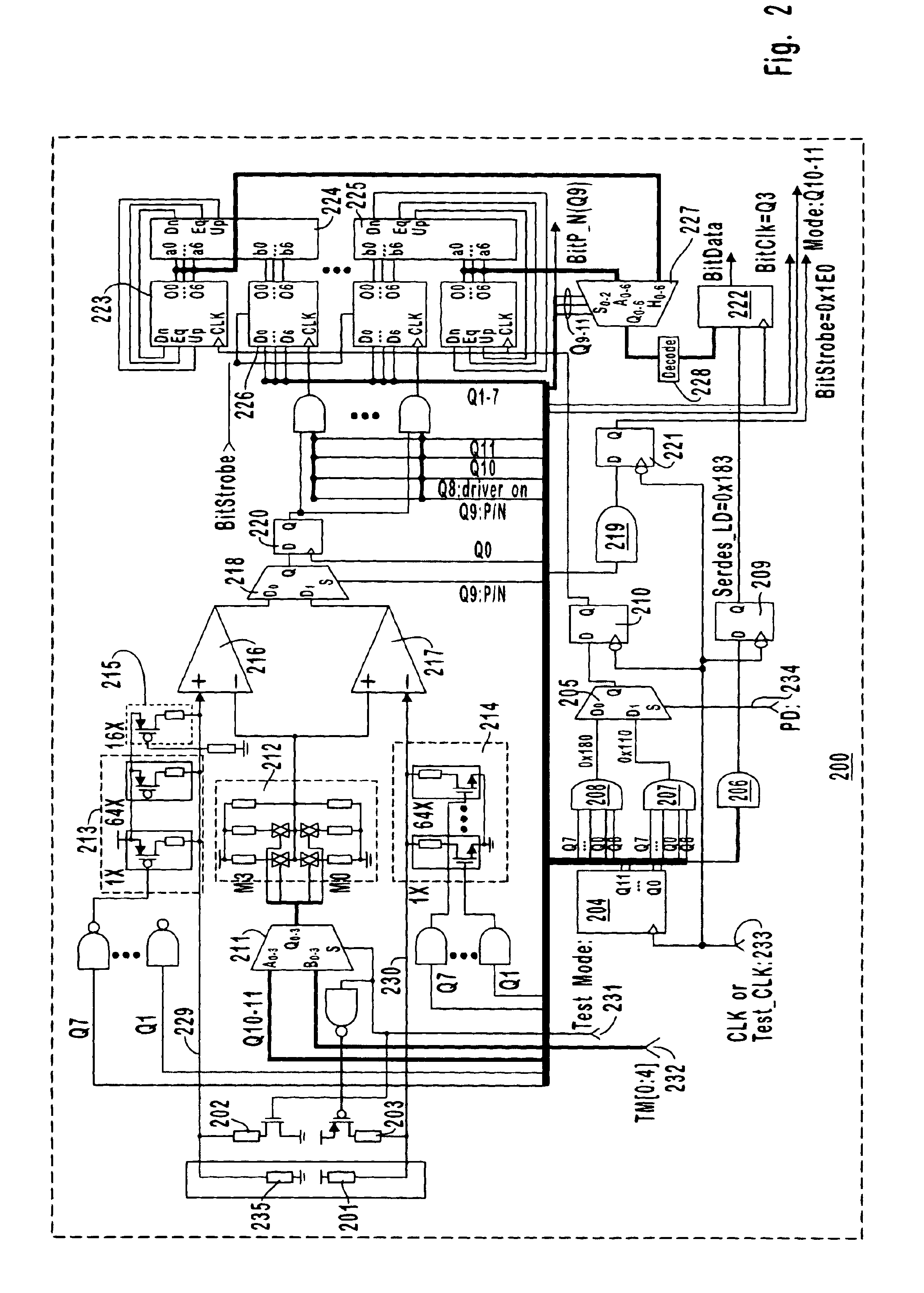
[0018]A noise attenuation circuit turns off only one of the fingers if the controller circuit determines that more impedance is needed even if turning off only one of the fingers would not result in the configuration of the DCI driver circuit determined by the controller circuit. Likewise, the noise attenuation circuit turns on only one of the fingers if the controller circuit determines that less impedance is needed even if turning on only one of the fingers would not result in the configuration of the DCI driver circuit determined by the controller circuit. While it may take more configuration updates to reach the desired matched impedance, the noise introduced to the input / output node is reduced since only one finger is turned on or off for each configuration update.
[0020]Less frequent updates during normal operation reduces the impact of switching noise on the input / output node. Furthermore, less frequent configuration updating may likely suffice so long as the frequency is still often enough that matched impedance may be generally maintained despite supply voltage fluctuations, process corners, temperature changes, and applied input / output voltage changes.

Problems solved by technology

Accordingly, DCI controllers that determine which fingers of the DCI driver should be on or off by assuming a fixed applied voltage may improperly cause the DCI driver to have inaccurate output impedances.
Having a significant number of fine fingers undesirably increases layout area and routing traffic.
Reducing the impedance of each fine finger is undesirable because for a given accuracy, the fine FETs 601 should be as small as possible to have a certain high impedance.
Therefore when the layout area and the routing channel is tight, it becomes very difficult or even impossible for conventional DCI drivers to keep the matched impedance over the entire supply voltage and temperature range.
Engaging coarse tuning during normal operation of drivers can be undesirable due to noise concern generated by SSO (Simultaneous Switching Output).
In particular, due to inductive effects, switching coarse FETs 602 may degrade the signal provided on the input / output node.

Method used


Image

  • Digitally controlled impedance driver matching for wide voltage swings at input/output node and having programmable step size
  • Digitally controlled impedance driver matching for wide voltage swings at input/output node and having programmable step size
  • Digitally controlled impedance driver matching for wide voltage swings at input/output node and having programmable step size

Examples


Embodiment Construction

[0029]The principles of the present invention are directed towards a Digitally Controlled Impedance (DCI) driver that is configured to drive a signal on its input / output node while at the same time controlling its own output impedance looking into the input / output node to closely match the input impedance of the load coupled to the input / output node. Such impedance matching greatly improves the quality of the signal that the DCI driver asserts on the input / output node.

[0030]FIG. 1 illustrates a DCI driver 100 in accordance with one embodiment of the present invention. The DCI driver 100 includes multiple fingers 111(1) through 111(n+p−1) and 112(1) through 112(n+p−1), where “n” and “p” are positive integers. The output impedance of the DCI driver 100 is controlled by configuring the multiple fingers so that the appropriate fingers are on and off to obtain the desired output impedance.

[0031]Each finger 111(1) through 111(n+p−1) includes a p-type Field Effect Transistor (pFET) unit as...


PUM


Abstract

A digitally controlled impedance driver circuit including a number of fingers, some of which having FETs and series resistors sized in binary or other differential ratios, and some of the higher power FETs being sized in equal ratio and perhaps sharing a series resistor. A DCI controller circuit periodically determines a configuration of the DCI driver circuit that would result in the DCI driver circuit approximating a target impedance. Each time the DCI controller circuit does this, a comparator determines if the impedance of the DCI driver circuit should be increased or decreased. A noise attenuation circuit turns off (or on) only one of the high power fingers if the controller circuit determines that more (or less) impedance is needed even if turning off (or on) only one of the fingers would not result in the configuration of the DCI driver circuit determined by the controller circuit.

Description

BACKGROUND OF THE INVENTION[0001]1. The Field of the Invention[0002]The present invention relates to a digitally controlled impedance driver that performs dynamic impedance matching for a wide range of voltage swings at the input / output node and that has a programmable step size.[0003]2. Background and Related Art[0004]Electronic circuits have revolutionized the way people work and play and have contributed enormously to the advancement of humankind. A large portion of the utility of electronic circuits is that they are designed to apply appropriately configured and timed signals to a load. A driver circuit is that portion of the circuit that physically applies the signal to the load. In order to reduce reflection and thereby improve the quality of the applied signal, the output impedance of the driver circuit should closely match the input impedance of the load.[0005]Digitally Controlled Impedance (DCI) matching techniques are one class of techniques that may be used to provide som...

Claims


Application Information

Patent Timeline
Patent Type & Authority Patents(United States)
IPC IPC(8): H03K19/00
CPCH03K19/0005
Inventor LI, ZHONGMINRUUD, TROYRASMUSSEN, BRYCEMO, SHAN
Owner SEMICON COMPONENTS IND LLC
Learn More