
High density, area array probe card apparatus

a probe card and high density technology, applied in the field of integrated circuit testing, can solve the problems of high cost, time-consuming and laborious, and the needle contact probe card is nearly impossible to achieve high density, and achieves the effect of high resolution, low change in position during testing, and rapid response cycle tim

Inactive Publication Date: 2005-06-14
TEXAS INSTR INC
View PDF1 Cites 66 Cited by
  • Summary
  • Abstract
  • Description
  • Claims
  • Application Information

AI Technical Summary

Benefits of technology

[0010]It is another object of the invention to provide a probe card contact apparatus which can be manufactured rapidly and economically.
[0011]It is yet another object of the invention to provide a probe card apparatus having thermal expansion similar to that of the semiconductor device to be tested so that contact is not compromised as a result of chip heating during testing.
[0015]The leads are fanned from the tightly spaced chip or inner contacts to the more generously spaced outer contacts which connect to a probe card. The design of a particular IC's input / output pads is input to a computer controlled laser. The fine beam of current technology lasers easily meets the tight pitch requirements of area array pads both in current production and in plans for the future. By use of a highly conductive, somewhat ductile metal, such as tin, and / or copper and tin, low inductance leads may be etched in a dense pattern by a fine beam laser. The conductors and pads have a thin, electroless plating of a noble metal, such as gold to provide environmental protection, and a bondable surface.
[0018]High resolution, ease and low cost of fabrication, and pattern customizing are achieved by software input of the design into a fine beam laser which ablates excess metal from a metal coated film. Rapid response cycle time is achieved by inventory of a substrates, and unpatterned metallized film. Laser processing is a significant factor in the ability to respond rapidly to the need for new probe cards designs, and the manufacture of high performance, high density probe card apparatus.

Problems solved by technology

This is accomplished by bending the needles after they are mounted on the probe card, which is laborious, time consuming, and expensive.
However, the close spacing necessary for testing some chips cannot be achieved with conventional needle contacts.
In particular, needle contact probe cards are nearly impossible for high density, area array bond pads on ICs.
The tight pitch of probe needles and the angles of their projection are extremely difficult to manufacture, and in turn insures a high cost.
Further, maintenance of such cards adds significantly to the cycle time of testing.
The issue of uniform contact, as well as alignment is aggravated by thermal expansion of the membrane because very often the chip generates a significant amount of heat during the testing procedure.
Further, photolithography definition of the leads adds cost to the testing procedure, not only as a result of the initial cost and multiple steps involved, but also because new artwork and masks are required for each new device and / or change, thus adding to cycle time for production.
Thin film conductors have an added risk of increased inductance to the circuit, which is a significant issue for testing high speed devices.
On the other hand, high resistivity of some probe needles, conductor traces, and multiple connections between needles, conductors on the probe card and those to the probe head can also lead to inductance values which impact the accuracy of chip testing.

Method used


Image

  • High density, area array probe card apparatus
  • High density, area array probe card apparatus
  • High density, area array probe card apparatus

Examples


Embodiment Construction

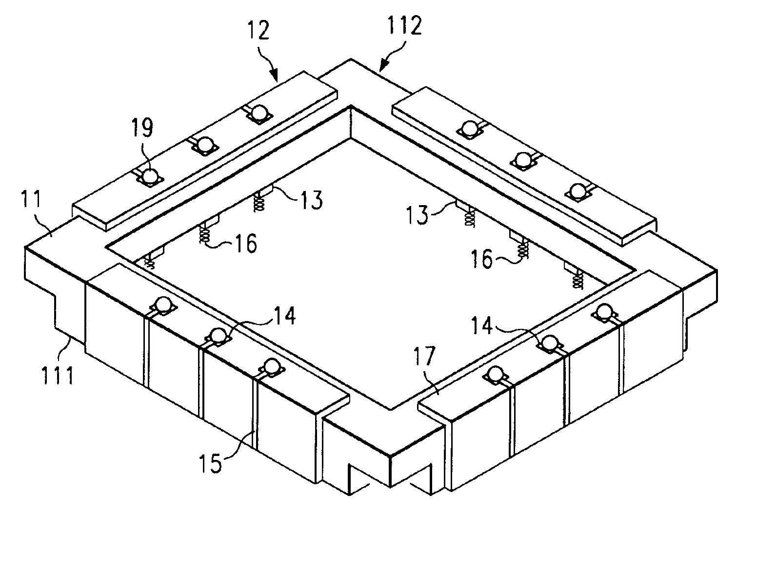
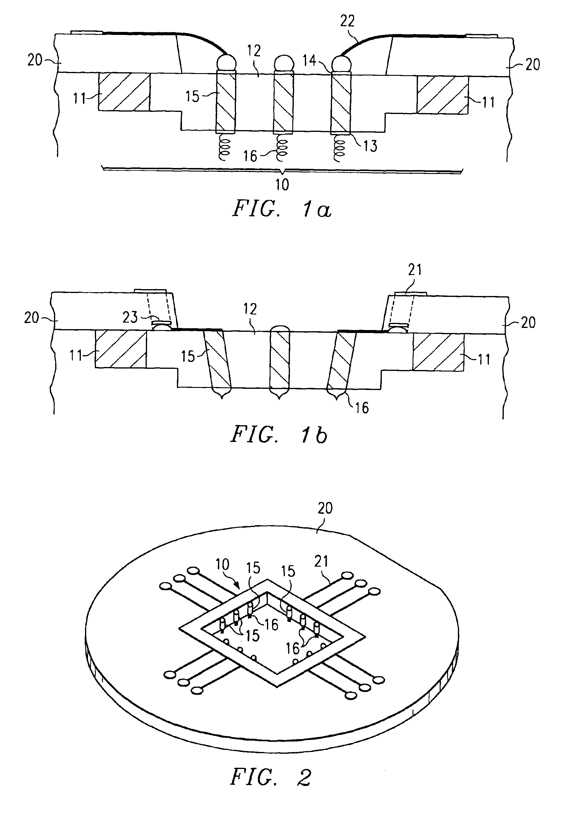
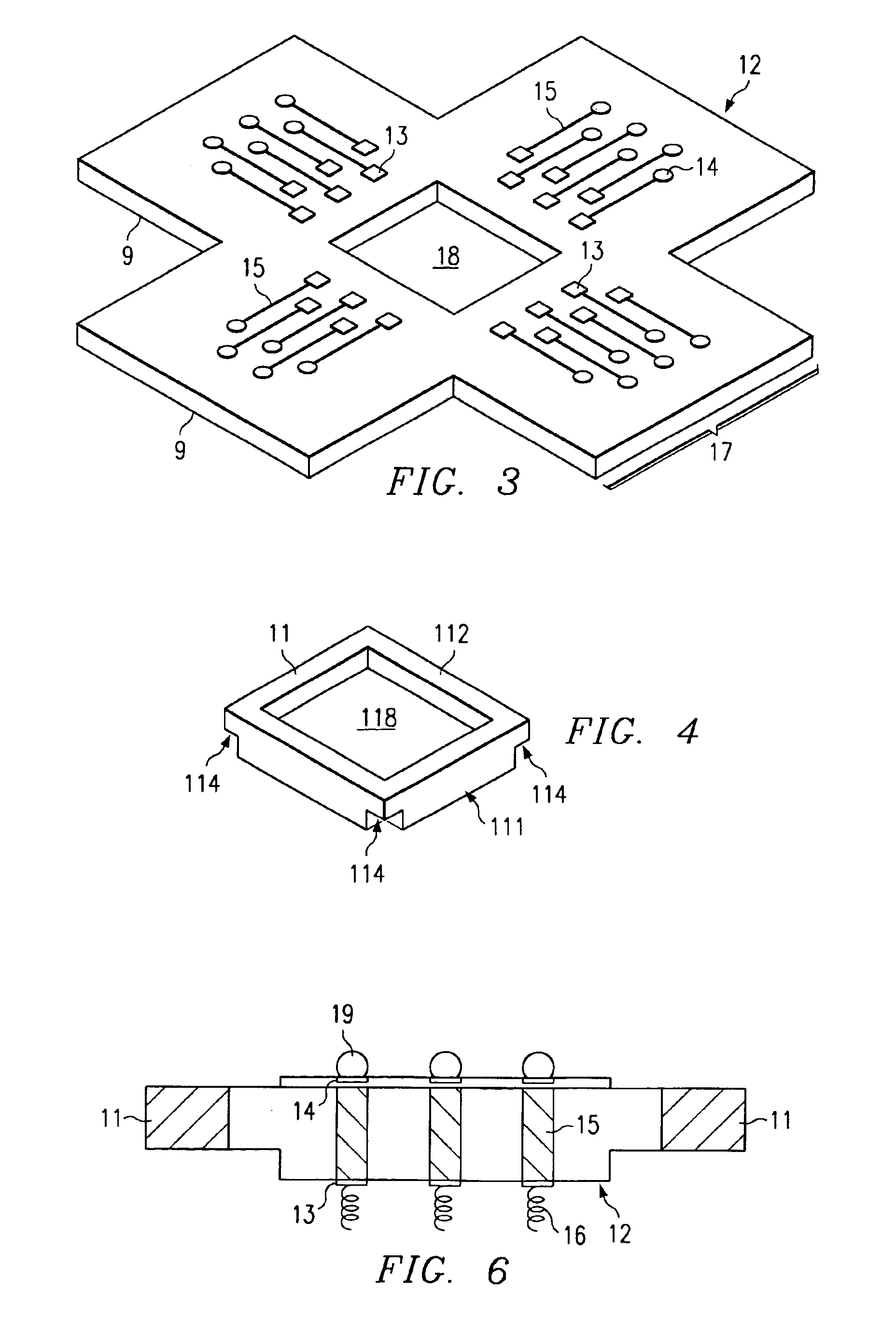
[0028]FIGS. 1a and 1b are cross sections of,the probe contact apparatus 10 of the current invention positioned in a probe card 20. FIG. 2 is a top view of the probe card 20 with the probe contact apparatus 10 only partially visible. In FIG. 1a, a cross section of an embodiment of the probe apparatus 10 includes a rigid substrate 11, a flexible dielectric film 12 extending from the first surface of the substrate around the edges and onto the second surface, and a plurality of contact pads 13, 14 on each end of conductive leads 15 formed on the film. Attached to the fine pitch contacts 13 on the first surface of the apparatus are protruding contact elements 16. These contact elements 16 are positioned to mirror the input / output pads of an integrated circuit under test (not shown). The position of contact pads 14 on the second surface corresponds to terminals of a probe card. In FIG. 1a, the terminals of the probe card are needle type probes 22. Alternately in FIG. 1b, contact is made ...


PUM

PropertyMeasurementUnit
Thicknessaaaaaaaaaa
Dielectric polarization enthalpyaaaaaaaaaa
Electrical inductanceaaaaaaaaaa

Abstract

A probe card apparatus comprising a rigid substrate having thermal expansion characteristics near that of silicon, laminated with a flex film having laser patterned leads and contact pads, and contact elements comprising noble metals protruding from two major surfaces, the first mirroring the closely spaced chip pads, and the second aligned to the more generously spaced probe card pads, providing an accurate and reproducible, low cost, rapidly fabricated probe contact device, capable of contacting very high density bond pads in either area array or perimeter locations, of being electrically optimized, and readily maintained.

Description

[0001]This application claims the benefit of the filing date of an earlier-filed provisional application No. 60 / 219,717 filed on Jul. 19, 2000.FIELD OF THE INVENTION[0002]This invention relates to testing of integrated circuits, and more particularly to probe card apparatus for testing of the integrated circuits.DESCRIPTION OF PRIOR ART[0003]Integrated circuits (ICs) are formed as multiple, identical, discrete chips on a semiconductor crystal wafer. Each of the integrated circuit chips is usually tested to determine whether or not it functions as intended prior to cutting the wafer into individual chips. Typically, the chips are tested by computer operated test apparatus that exercises the circuits on the chips, using a testing process commonly referred to as multiprobe testing.[0004]Conventional multiprobe testing employs a probe card which includes a plurality of electrical leads terminating in needles, which in turn make contact with input / output contacts of the various circuit e...

Claims


Application Information

Patent Timeline
IPC IPC(8): G01R1/073G01R31/26H01L21/66
CPCG01R1/07314Y10T29/49204
Inventor WILSON, LESTERRINCON, REYNALDO M.BROZ, JERRYARNOLD, RICHARD W.
Owner TEXAS INSTR INC
Learn More