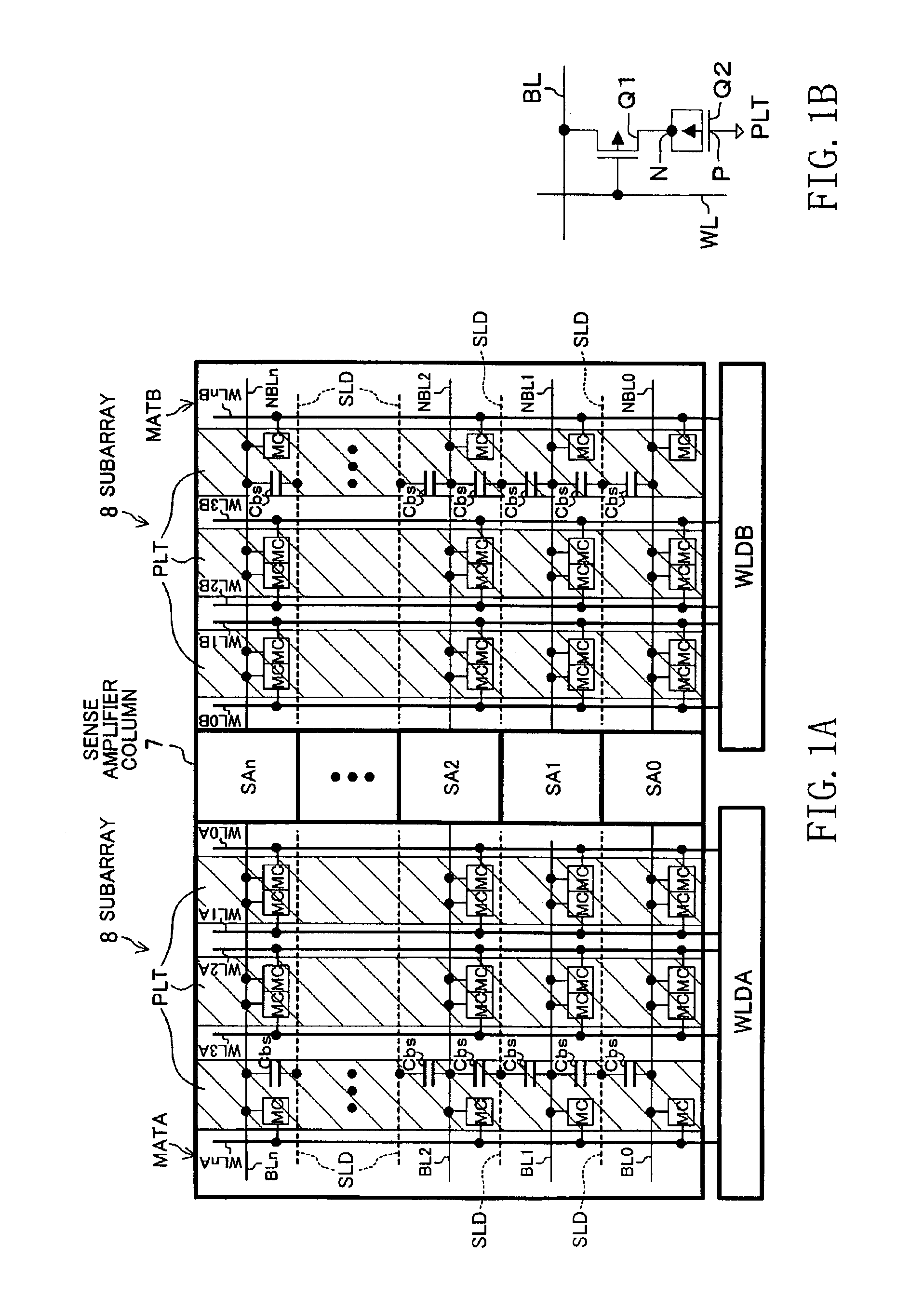
Semiconductor memory device in which bit lines connected to dynamic memory cells extend left and right of sense amplifier column
a memory device and dynamic memory technology, applied in semiconductor devices, digital storage, instruments, etc., can solve the problems of insufficient stability of plate potentials, interference noise between adjacent bit lines, and noise that is not negligible on the plate electrodes, so as to reduce the relative variation between the pair transistors and increase the operation stability of the sense amplifier circuit.
- Summary
- Abstract
- Description
- Claims
- Application Information
AI Technical Summary
Benefits of technology
Problems solved by technology
Method used
Image
Examples
embodiment 1
[0052]FIG. 14 schematically shows the whole layout of a semiconductor memory device according to Embodiment 1 of the present invention.
[0053]The figure shows a memory chip 10 that constitutes a dynamic RAM. In this memory chip 10, reference numerals 1 represents a memory control circuit block disposed on the left end in the figure, numeral 2 represents a read and write amplifier and a column-selecting circuit block disposed on the right of the memory control circuit block in the figure, numeral 3 represents a row decoder and word line-driving circuit block disposed in the center and along the longitudinal direction of the memory chip 10, numeral 4 represents an internal power-generating circuit block disposed on the right end in the figure, and numeral 5 represents two memory blocks separately disposed above and below the row decoder and word line-driving circuit block 3.
[0054]The memory block 5 has memory arrays 6 that are disposed so that each row along the longitudinal direction ...
embodiment 2
[0092]A semiconductor memory device according to Embodiment 2 of the invention is described below. The present embodiment relates to an improvement of the layout configuration of sense amplifier circuits and bit lines in a dynamic RAM.
[0093]Before detailing the present embodiment, the layout configuration shown in FIG. 9 is described. In the figure, BL0, BL1, NBL0, and NBL1 denote respective bit lines; the bit lines BL0 and NBL0 constitute a complementary bit line pair, and the bit lines BL1 and NBL1 constitute another complementary bit line pair. The bit lines BL0, BL1, NBL0, and NBL1 are formed in the same metal wiring layer (a first metal wiring layer), both in the regions of the subarrays 8 and in the region of the sense amplifier.
[0094]NSA0, NSA1, PSA0, and PSA1 denote pair transistors that form respective pairs in the sense amplifier circuit (CMOS latch circuit). In the bit line pairs (BL0, NBL0) and (BL1, NBL1), ones of the bit lines BL0 and BL1 and the other ones of the bit ...
embodiment 3
[0107]Next, another example of the present invention is described with referent to FIG. 13. The present embodiment pertains to an improvement of a latch circuit in the sense amplifier circuit.
[0108]First, a conventional configuration is described. FIG. 12 is a schematic view of a conventional layout configuration of pair transistors that constitute a latch circuit in a sense amplifier circuit. In the figure, OD denotes an active region, Q1 and Q2 denote pair transistors that form a pair in the latch circuit, BL and NBL denote a pair of complementary bit lines, and S denotes a common source of the pair transistors Q1 and Q2. One of the bit lines BL is connected to the gate of one of the transistors Q1 and the drain of the other transistor Q2, and the other bit line NBL is connected to the gate of the other transistor Q2 and the drain of the one of the transistors Q1. The gate electrodes G1 and G2 of the respective pair transistors Q1 and Q2 are disposed parallel to each other in the ...
PUM
 Abstract
Description
Claims
Application Information
 - R&D
- Intellectual Property
- Life Sciences
- Materials
- Tech Scout
- Unparalleled Data Quality
- Higher Quality Content
- 60% Fewer Hallucinations
Browse by: Latest US Patents, China's latest patents, Technical Efficacy Thesaurus, Application Domain, Technology Topic, Popular Technical Reports.
© 2025 PatSnap. All rights reserved.Legal|Privacy policy|Modern Slavery Act Transparency Statement|Sitemap|About US| Contact US: help@patsnap.com


