Power scalable waveguide amplifier and laser devices
a waveguide amplifier and laser device technology, applied in the field of optical amplifiers and lasers, to achieve the effect of avoiding undesirable nonlinear effects and preserving polarization
- Summary
- Abstract
- Description
- Claims
- Application Information
AI Technical Summary
Benefits of technology
Problems solved by technology
Method used
Image
Examples
embodiment 40
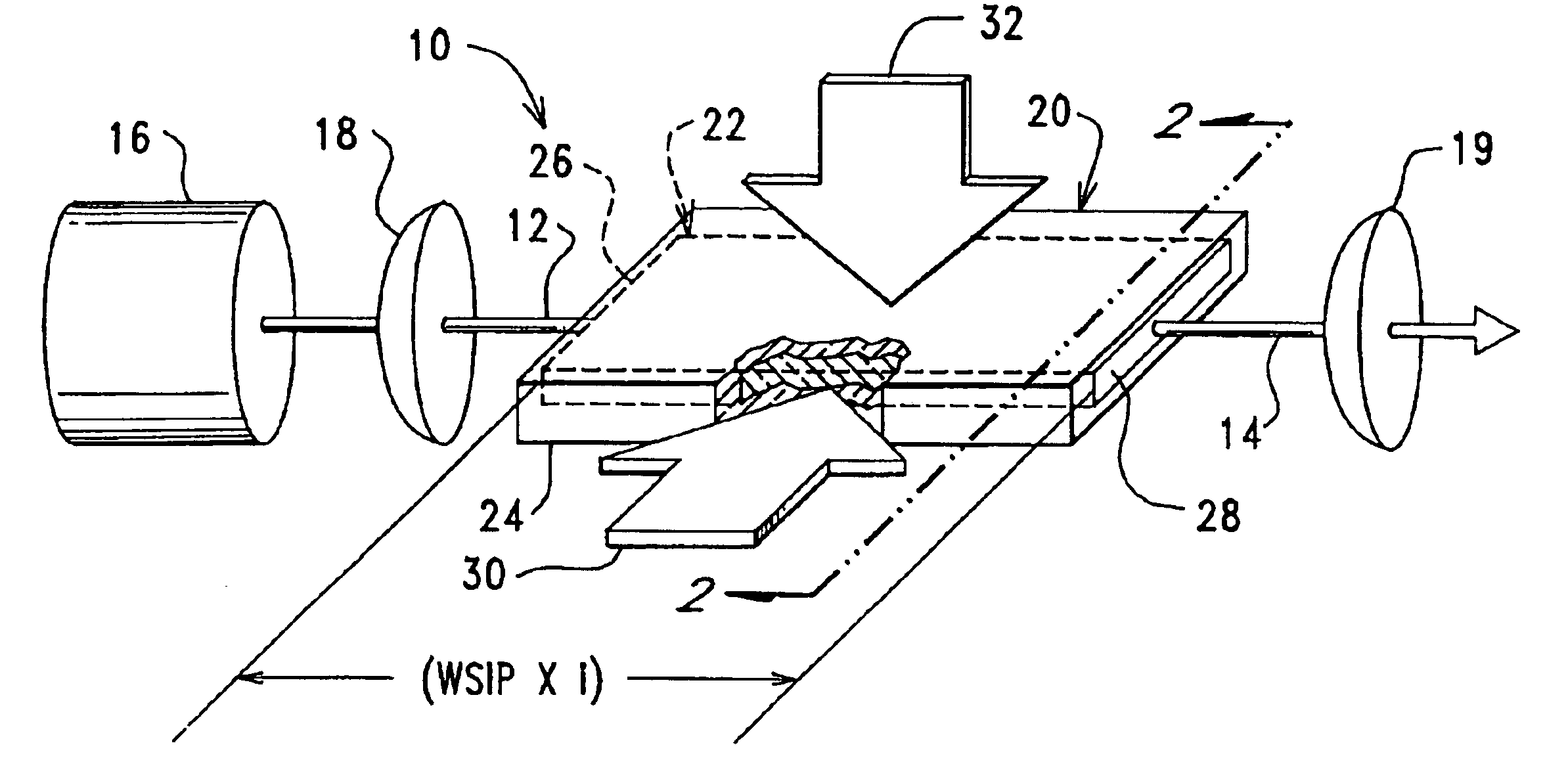
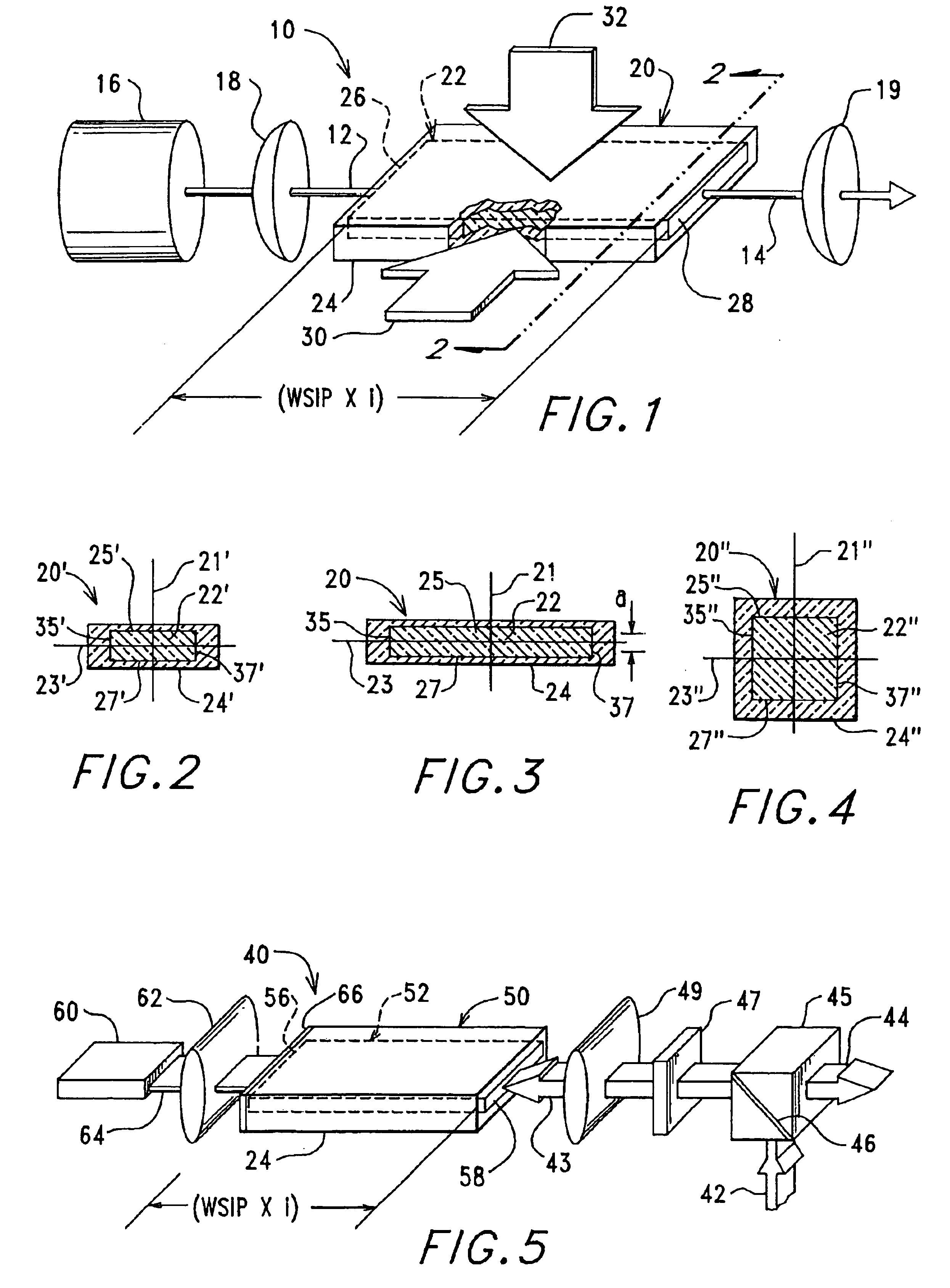
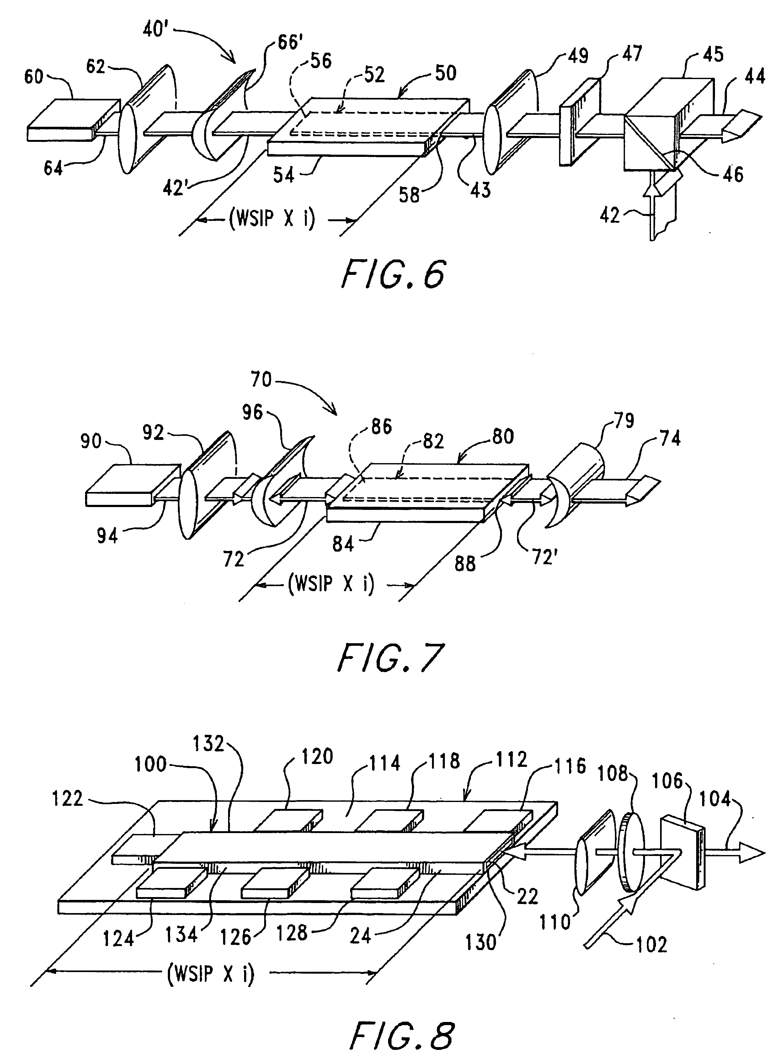
[0083]The high-power optical amplifier 10 of this invention shown in FIG. 1 and described above is just one simple embodiment illustrating the use of a multi-mode, rectangular, re-imaging waveguide with a core comprising a gain or mixing medium for amplifying a light beam or mixing with other beams. There are, of course, many other useful amplifier configurations and embodiments that will occur to persons skilled in the art, once they understand the principles of this invention. For example, a double-pass optical amplifier embodiment 40, in which the light beam 42 being amplified is passed twice through the multi-mode, rectangular waveguide 50 to thereby extract even more energy from the gain medium in the waveguide core 52. In this example, the gain medium that comprises the core 22, such as Nd:YAG, is pumped with light energy 64 with, for example, a laser diode 58 coupled into the core 22 by a lens focusing system 59, which focuses the light 64 produced by the laser diode 58 onto ...
embodiment 160
[0098]In another multi-mode, rectangular waveguide embodiment 160, illustrated in FIG. 11, which waveguide 160 can be used according to this invention for both optical amplifier and laser resonator applications, the waveguide 160 comprises a core 162 comprising gain medium sandwiched between two cladding layers 164, 166. Two mirrors or reflective coatings 168, 170 cover portions of the lateral edges of the waveguide 160, and the input beam 172 is directed at an angle into the first waveguide aperture or face 176 toward the opposite reflective coating 168. The beam 172 is reflected by coating or mirror 170, which also reflects its back toward mirror 168, etc. Consequently, the beam 172 propagates through the waveguide 160 in a zig-zag path that is much longer than a straight path through the waveguide 160. Eventually, the beam emerges as an output beam 174 from a second aperture or face 178 that is not covered by the reflector 168. The longer path of the beam 172 through the waveguid...
second embodiment
[0109]FIG. 15 depicts the present invention, in which a plurality waveguides 250 may be stacked or otherwise configured in accordance with other features disclosed herein. Input beams 252, represented as arrows, may be introduced to an optical aperture, entrance face, or cross-section of each waveguide 256 for multiple beam applications in accordance with the present invention. In some embodiments, relative phase shifts between waveguides may be deterministically controlled, for example, by phase shift elements, in order to produce a desired wavefront, either for hollow or dielectric core waveguides. FIG. 12 further provides an embodiment of such stacked or configured waveguides, wherein a beam or image (depicted), for a plurality of beams or images, may be transmitted or input from one or a plurality of sources, for example a transmitter array or VCSEL, into a stacked waveguide, more particularly provided herein in FIG. 12 as a 2-dimensional waveguide array, potentially comprising ...
PUM
 Abstract
Description
Claims
Application Information
 - R&D
- Intellectual Property
- Life Sciences
- Materials
- Tech Scout
- Unparalleled Data Quality
- Higher Quality Content
- 60% Fewer Hallucinations
Browse by: Latest US Patents, China's latest patents, Technical Efficacy Thesaurus, Application Domain, Technology Topic, Popular Technical Reports.
© 2025 PatSnap. All rights reserved.Legal|Privacy policy|Modern Slavery Act Transparency Statement|Sitemap|About US| Contact US: help@patsnap.com


