
Method of forming a conductive contact

Inactive Publication Date: 2005-05-03
MICRON TECH INC
View PDF41 Cites 14 Cited by
  • Summary
  • Abstract
  • Description
  • Claims
  • Application Information

AI Technical Summary

Benefits of technology

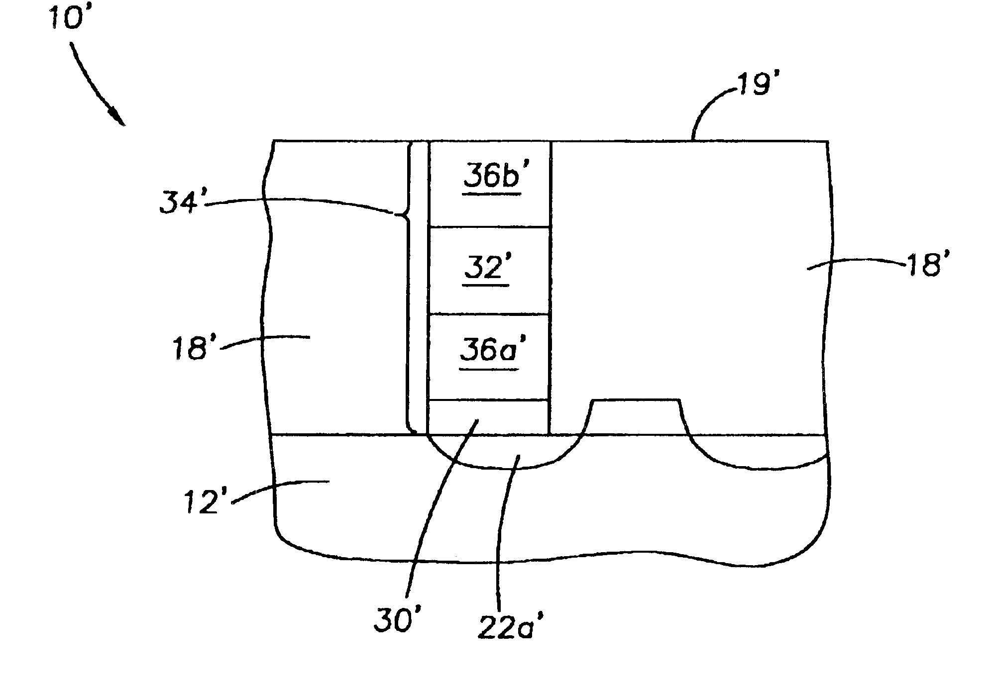
[0012]The present invention overcomes the problems of a pure TiCl4-based titanium nitride plugs or barrier film by incorporating diborane (B2H6) into the gas mixture to dope the TiCl4-based titanium nitride film during the deposition process. The addition of B2H6 to the precursor gas used to form the TiCl4-based titanium nitride film has been found to improve the mechanical properties of the resulting titanium nitride film with substantially no impact on its conductive properties. In particular, the gaseous mixture used to form the boron-doped, titanium nitride contacts comprises diborane (B2H6) in an amount effective to provide a contact having an amount of boron to provide a level of adhesion of the conductive contact to the insulative sidewalls of the contact opening to substantially eliminate peeling of the contact from the sidewalls and cracking of the body of the insulative layer. The mixture further includes an amount of ammonia (NH3) to provide the contact with a level of nitrogen effective to maintain the conductivity of the contact at a predetermined level for an effective electrical contact with a conductive or active area within the substrate to / from an active area within a semiconductor device and / or a memory or logic array.
[0013]However, one drawback of titanium nitride films formed from TiCl4, including the boron-doped films described herein, is that the chlorine (Cl2) within the formed contact can diffuse into an overlying material, for example, an overlying interconnect of aluminum, and corrode and ruin the device. It has been found that a high temperature anneal of the TiCl4-based titanium nitride film in a nitrogen-containing atmosphere, preferably ammonia (NH3), removes excess Cl2 from the contact material to overcome the diffusion problem. It has also been found that conducting a CMP process to remove excess material from the substrate prior to the anneal step avoids undesirable problems with cracking of the film layer and the wafer substrate.
[0023]Advantageously, the present film overcomes limitations of tungsten plug fills in high aspect ratio devices, with parametric data showing superior results compared to that of tungsten. The films also have a decreased level of undesirably components such as chlorine that become incorporated into the film upon deposition of precursor gases to form the film. The present method provides a process of removing undesirable components such as chlorine and the like, from a contact which overcomes problems in the art with cracking from anneal processing steps, and without adversely effecting other structures and devices formed on the substrate. The present invention provides processes for forming conductive contacts that are fast, simple and inexpensive to implement in semiconductor manufacturing.

Problems solved by technology

Pure TiCl4-based titanium nitride fills do not adhere well to the surface of insulative sidewalls of a contact opening, and can also cause the insulative layer to crack due, at least in part, to the pressure exerted when the thickness of the fill within the contact opening is about 200 angstroms or greater.
However, one drawback of titanium nitride films formed from TiCl4, including the boron-doped films described herein, is that the chlorine (Cl2) within the formed contact can diffuse into an overlying material, for example, an overlying interconnect of aluminum, and corrode and ruin the device.

Method used


Image

  • Method of forming a conductive contact
  • Method of forming a conductive contact
  • Method of forming a conductive contact

Examples


example 1

[0061]A boron-doped TiCl4-based titanium nitride (TiN) contact was formed in a high aspect ratio opening of a BPSG layer, without removal of chlorine by RTP anneal. The flow of diborane (B2H6) was varied over a range to test the change in thermal stress (Gdynes / cm2) of the boron-doped, TiCl4-based TiN contact on the BPSG insulative layer.

[0062]A wafer fragment was provided that had a silicon substrate layer and an overlying layer of BPSG. A contact opening was formed through the BPSG layer. The aspect ratio of the opening was 10:1.

[0063]The TiCl4-based TiN film was deposited by thermal CVD at a pressure of 10 Torr using a Centura system, available from Applied Materials company of Santa Clara, Calif. The precursor gases were flowed into the reactor as follows: 340 sccm TiCl4, 200 sccm NH3, 3000 sccm argon (Ar), and 2000 sccm gaseous nitrogen (N2). The diborane (B2H6) was flowed into the reactor at a rate ranging from 200 sccm to 600 sccm. Data was measured at two different temperatu...

example 2

[0065]A boron-doped TiCl4-based titanium nitride (TiN) contact was formed in a high aspect ratio opening of a BPSG layer according to the method of the invention. A boron-doped TiN film was formed in a contact opening (10:1 aspect ratio) in a BPSG layer overlying a silicon substrate, as described in Example 1.

[0066]Excess titanium nitride film material was removed from the surface of the BPSG layer by conventional CMP, leaving the film material within the contact opening. The wafer was then subjected to a high temperature anneal by rapid thermal processing (RTP) in an ammonia (NH3) atmosphere at 750° C. for 25 seconds. PEELS micrographs showed differences in the chlorine (Cl2) content of the boron-doped titanium nitride material before and after the high temperature anneal.


PUM


Abstract

Conductive contacts in a semiconductor structure, and methods for forming the conductive components are provided. The method comprises depositing a conductive material over a substrate to fill a contact opening, removing excess material from the substrate leaving the contact within the opening, and then heating treating the contact at a high temperature, preferably with a rapid thermal anneal process, in a reactive gas to remove an undesirable component from the contact, for example, thermal annealing a TiCl4-based titanium nitride in ammonia to remove chlorine from the contact, which can be corrosive to an overlying aluminum interconnect at a high concentration. The contacts are useful for providing electrical connection to active components in integrated circuits such as memory devices. In an embodiment of the invention, the contacts comprise boron-doped and / or undoped TiCl4-based titanium nitride having a low concentration of chlorine. Boron-doped contacts further possess an increased level of adhesion to the insulative layer to eliminate peeling from the sidewalls of the contact opening and cracking of the insulative layer when formed to a thickness of greater than about 200 angstroms in a high-aspect-ratio opening.

Description

CROSS-REFERENCE TO RELATED APPLICATIONS[0001]This application is a division of U.S. application Ser. No. 09 / 941,533, filed Aug. 29, 2001.FIELD OF THE INVENTION[0002]The present invention relates to the field of semiconductor device fabrication, and more particularly to methods for making conductive contacts in the formation of a semiconductor device.BACKGROUND OF THE INVENTION[0003]As semiconductor fabrication moves toward maximizing circuit density, electrical components are formed at a number of layers and different locations. This requires electrical connection between metal layers or other conductive layers at different elevations in the substrate. Such interconnections are typically provided by forming a contact opening through insulating layer to the underlying conductive feature. With increasing circuit density, the dimensions of openings for electrical contacts become narrower and deeper, posing a challenge to provide adequate conductive fill within high aspect ratio opening...

Claims


Application Information

Patent Timeline
IPC IPC(8): H01L21/285H01L21/02H01L21/70H01L23/48H01L23/485H01L21/768
CPCH01L21/28556H01L21/76877H01L23/485H01L2924/0002H01L2924/00
Inventor DERRAA, AMMAR
Owner MICRON TECH INC
Learn More