Accordingly, its developing assembly is large and heavy and also has complicate construction.
In this regard, the one-component developing
system does not require any carrier and such complicate construction, and can make the developing assembly itself compact, small-size and light-weight.
In addition, it does not require any replacement of carriers, and hence makes maintenance service unnecessary over a long period of times. On the other hand, the one-component magnetic developing
system is difficult to employ in color development because
pitch-black magnetic particles are used in toners, whereas the two-component developing
system enables control of delicate development condition by means of the concentration detection device and hence is preferably used in color development.
Though generated in a remarkably smaller quantity than that in
corona charging assemblies, a
discharge product is inevitably generated in principle, and hence difficulties due to active ions such as
ozone are unavoidable.
Hence, any attempt of direct-injection charging may inevitably cause a decrease in absolute chargeability, a contact unevenness due to shortage in contact performance and roller shape and a charging unevenness due to any deposits on the charging object member.
In the DC charging, however, it has been difficult to control the potential of the photosensitive member at the desired value because the resistance value of the contact charging member varies depending on environmental variations and also because the Vth varies with changes in
layer thickness caused by the abrasion of the photosensitive member.
However, even in such contact charging assemblies, its fundamental charging mechanism employs the phenomenon of
discharge from the contact charging member to the photosensitive member.
Also, when the AC charging is performed in order to achieve uniform charging, the
ozone may more be generated, the
electric field of AC
voltage may cause a vibrating
noise (AC charging sound) between the contact charging member and the photosensitive member, and any discharging may remarkably cause deterioration or the like of the surface of the photosensitive member.
Those having a
fiber density of about 100 fibers / mm2 are obtained relatively with ease, but are still insufficient for contact performance in order to perform well uniform charging by direct-injection charging.
In order to perform well uniform charging by direct-injection charging, the fur
brush charging assembly must be made to have a velocity differential from that of the photosensitive member; the difference being so large as to make
machine construction difficult.
This is not realistic.
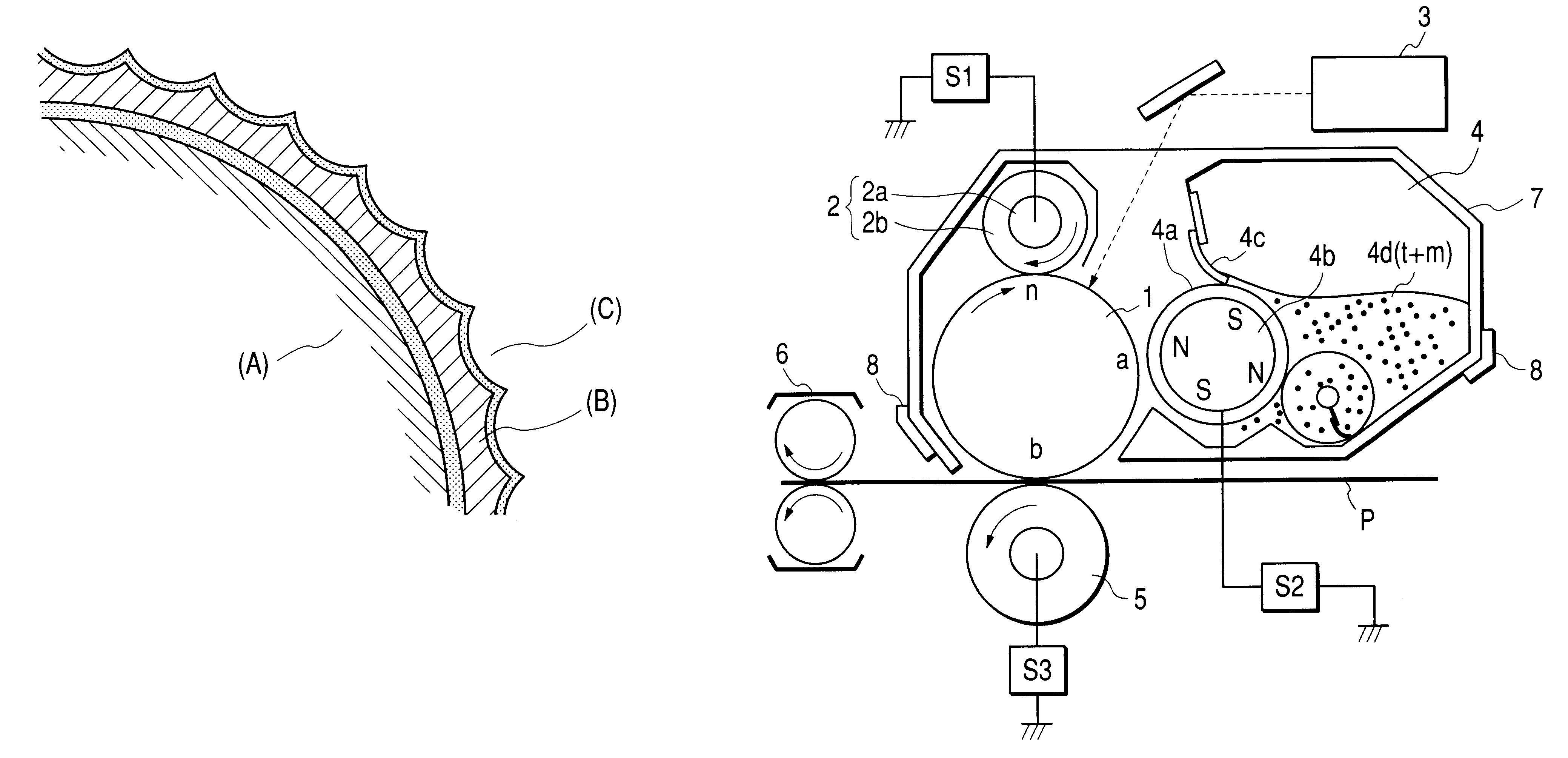
The magnetic-
brush charging, however, may also cause a difficulty that the conductive magnetic particles constituting the magnetic-
brush portion come off to adhere to the photosensitive member.
There, however, has been a problem that pressing a cleaning member against the latent-image-bearing member surface causes the latent-image-bearing member to wear to make the latent-image-bearing member have a
short lifetime.
This has been a
bottleneck in attempts to make apparatus compact.
In this sense, such techniques have not been satisfactory for various recording mediums.
However, in the cleaning-at-development or cleanerless process making use of a contact development system, its long-term service tends to cause deterioration of toner, deterioration of toner-carrying member surface and deterioration or wear of latent-image-bearing member surface, but any satisfactory solution has not been made for running performance.
Also, in the case of the charging method predominantly governed by the
discharge charging mechanism, the transfer residual toner may come to greatly adhere to the contact charging member because of any toner deterioration due to discharge energy.
Where any insulating toner commonly used has adhered to or migrated into the contact charging member, a lowering of charging performance may occur.
This lowering of uniform charging performance on the charging object member may lower the contrast and uniformity of electrostatic latent images after imagewise
exposure to cause difficulties such as a decrease in
image density and an increase in
fog. occur seriously.
However, where the transfer residual toner has adhered to or migrated into the contact charging member beyond the contact charging member's capacity to control toner's charge polarity, it becomes impossible to uniformly adjust the charge polarity of the transfer residual toner, making it difficult to collect the toner in the step of development.
Also, even where the transfer residual toner has been collected on the toner-carrying member by
mechanical force such as
rubbing, the transfer residual toner may adversely affect the triboelectric chargeability of toner on the toner-carrying member, resulting in a lowering of developing performance, unless the charge of the transfer residual toner has not uniformly been adjusted.
However, the contact charging used here also applies the discharge charging mechanism, which is not the direct injection charging mechanism, and has the above problem ascribable to the discharge charging.
Moreover, these proposals may be effective for keeping the charging performance of the contact charging member from lowering because of the transfer residual toner, but can not be expected to be effective for actively improving the charging performance.
Such image-forming apparatus have good cleaning-at-development performance and the waste toner can sharply be reduced, but involve a high cost and may damage the
advantage inherent in the cleaning-at-development system also in view of compact construction.
Accordingly, when the apparatus is used over a long period of time, difficulties such as smeared images due to
ozone products tend to come out.
Moreover, when the above construction is applied in cleanerless image-forming apparatus, any inclusion of the transfer residual toner makes it difficult for the
powder coated, to stand adhered uniformly to the charging member, so that the effect of carrying out uniform charging may lower.
However, the contact charging used here, or proximity charging, applies the discharge charging mechanism, which is not the direct injection charging mechanism, and has the above problem ascribable to the discharge charging.
Furthermore, when the direct injection charging mechanism is applied in the contact charging, the conductive fine particles can not be fed to the contact charging member in necessary quantity to cause faulty charging due to the influence of the transfer residual toner.
In the proximity charging, it is also difficult to uniformly charge the photosensitive member because of the large-quantity conductive fine particles and transfer residual toner, and the effect of leveling patterns of the transfer residual toner can not be obtained, to cause pattern ghost because the transfer residual toner may shut out pattern-imagewise
exposure light.
In the case of blast-treated developing sleeves, the surface unevenness tends to become worn and lessen as a result of long-time service.
It is known that, during its long-term service, toner particles and so forth having especially fine particle size are buried in sharp valleys of this surface (hereinafter this state in which the toner particles and so forth are buried is called “sleeve
contamination”) and the charging of toner is obstructed at that part to cause faulty images.
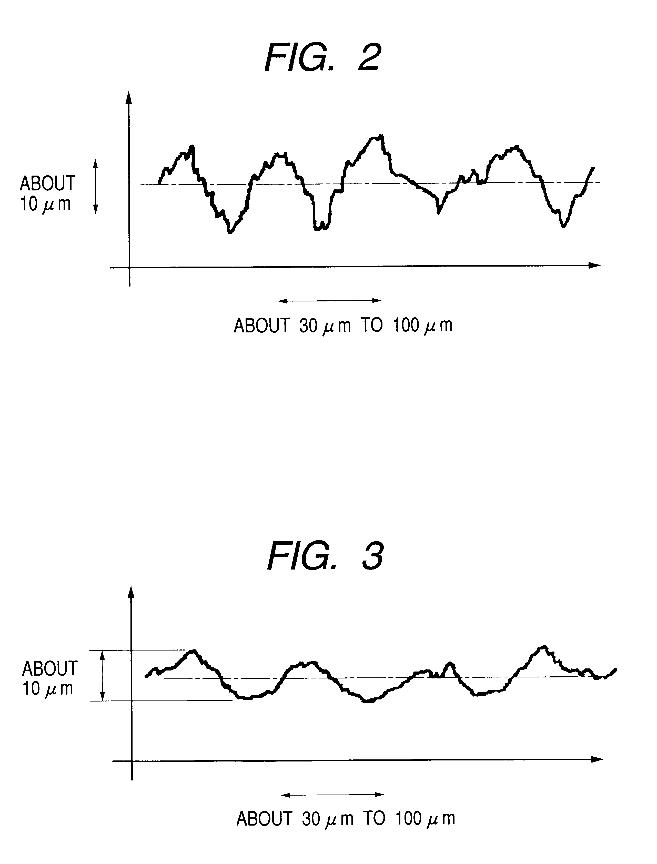
However, the aluminum sleeve has a
hardness as low as Hv of about 100, and hence the surface unevenness may easily become worn as a result of use, so that the unevenness may lessen at an early stage.
This has proved to tend to cause the sleeve
contamination much more than ever.
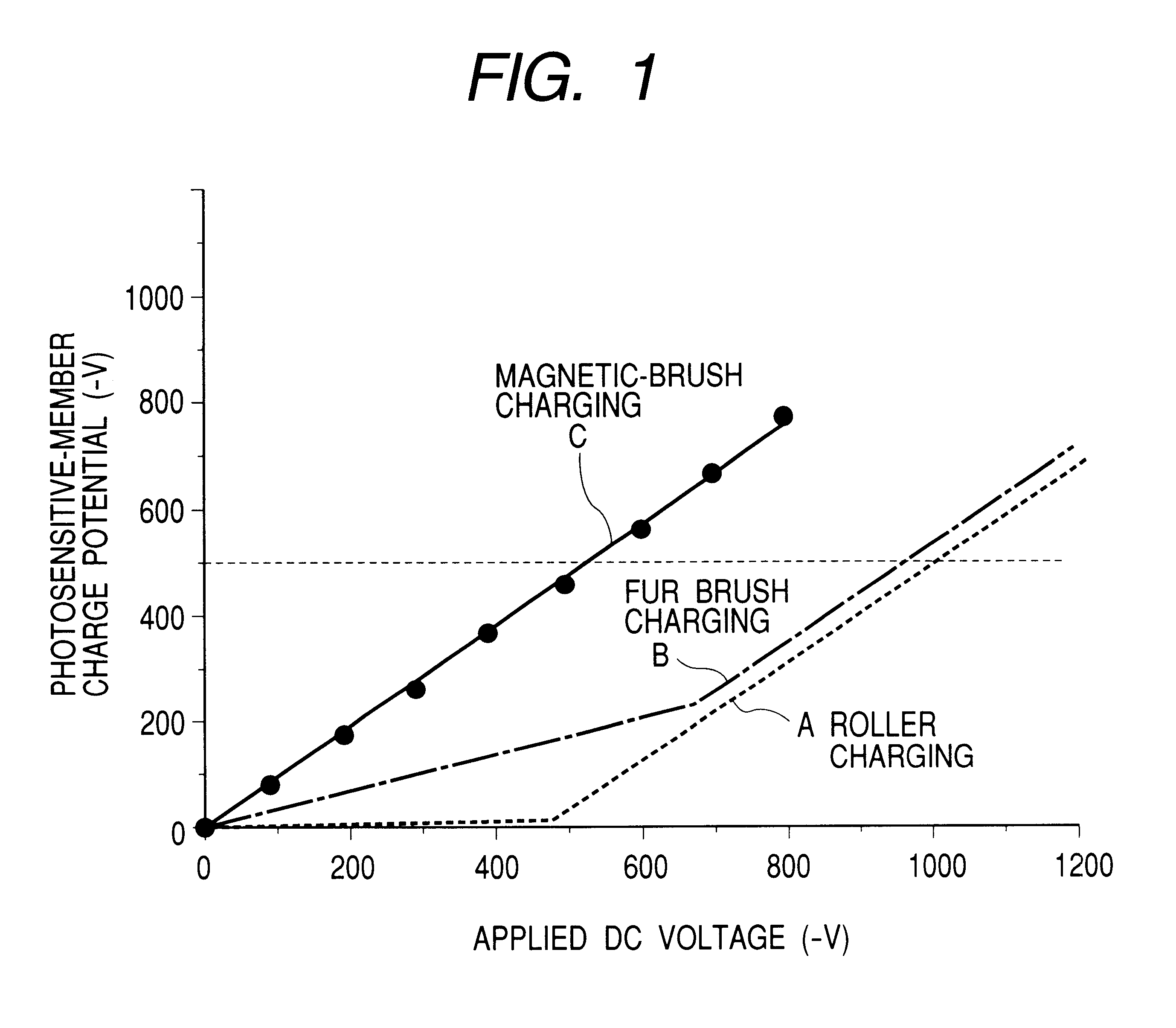
In the profile shown in FIG. 4, in the case of toners with a
large particle diameter, any particles do not enter any cracks in large hills and dales in the roughness profile curve, namely, do not enter small valleys as exemplified by valleys a, b and c. However, with an decrease in particle
diameter of the toner, toner particles entering the small valleys a, b and c may increase to cause sleeve contamination, as so considered.
Such particles enter the small valleys a, b and c. Of course, any finer
powder in toner may be
cut away in order to lessen smaller toner particles, but it is impossible under the existing conditions to remove them completely.
As stated previously, even without making toners have smaller particle
diameter, charge obstruction on toner also tends to occur because of even a slight sleeve contamination when toners having a low chargeability are used, bringing about difficulties such as density loss.
This sleeve ghost has a tendency that, the higher charging performance the external additive has, the more easily it appears.
Hence, the toner present above the part where this fine-
powder layer has been formed comes to have a low developability because it is not sufficiently triboelectrically charged with the developing sleeve surface, so that this may appear as the sleeve ghost on images.
Besides the above phenomenon of sleeve ghost, a problem may arise such that areas having a
low density occur in vertical lines on images obtained by development.
As the result, continuing
copying or printing in this state accelerates the deterioration of the toner to cause a decrease in density (density loss) at such areas.
The smaller the toner particle diameter is, the more the
fading is liable to occur.
Under existing circumstances, studies have not yet sufficiently been made.
