
Bulk laminated amorphous metal inductive device

a technology of inductive devices and amorphous metals, applied in the direction of transformers/inductances, magnetic cores, magnetic cores/yokes, etc., can solve the problems of high rapid failure, and difficult or impossible physical properties of conventional fabrication techniques, so as to improve resistance and reduce tooling and manufacturing costs , the effect of low resistan

Inactive Publication Date: 2005-03-29
METGLAS INC
View PDF50 Cites 36 Cited by
  • Summary
  • Abstract
  • Description
  • Claims
  • Application Information

AI Technical Summary

Benefits of technology

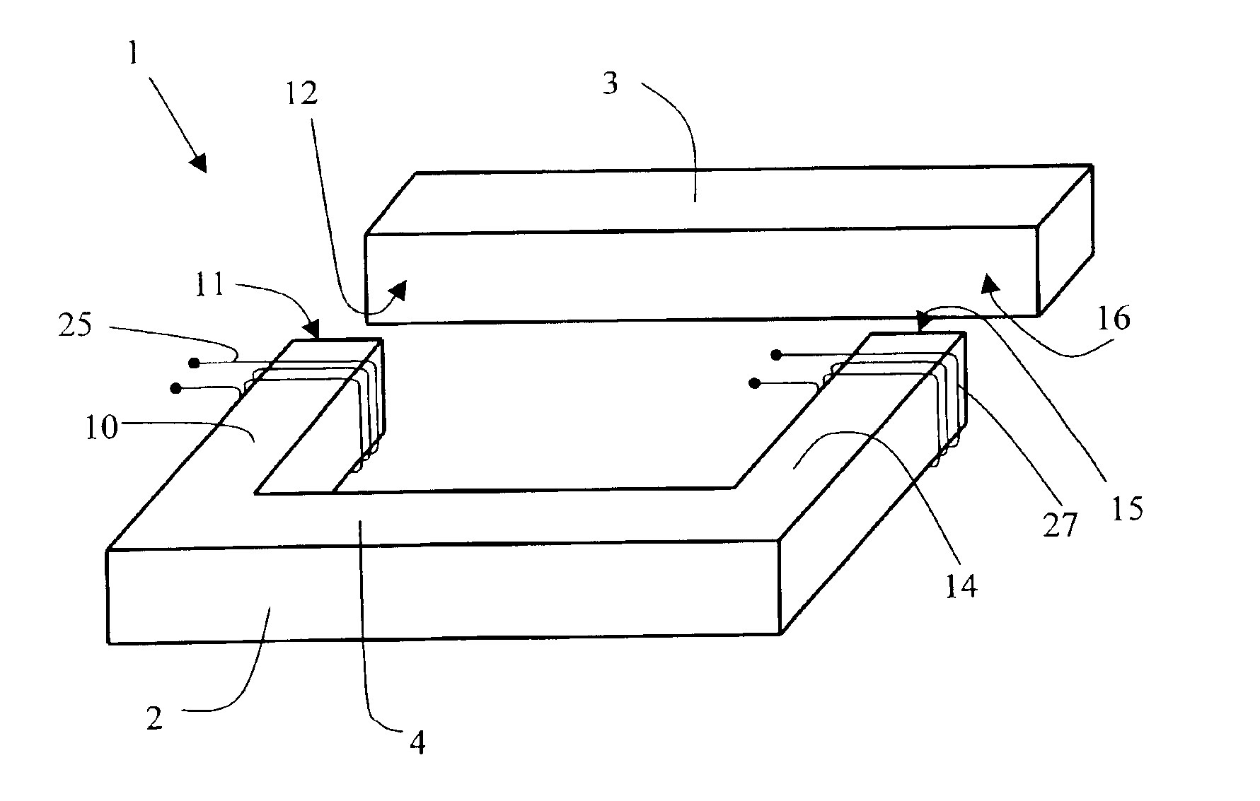
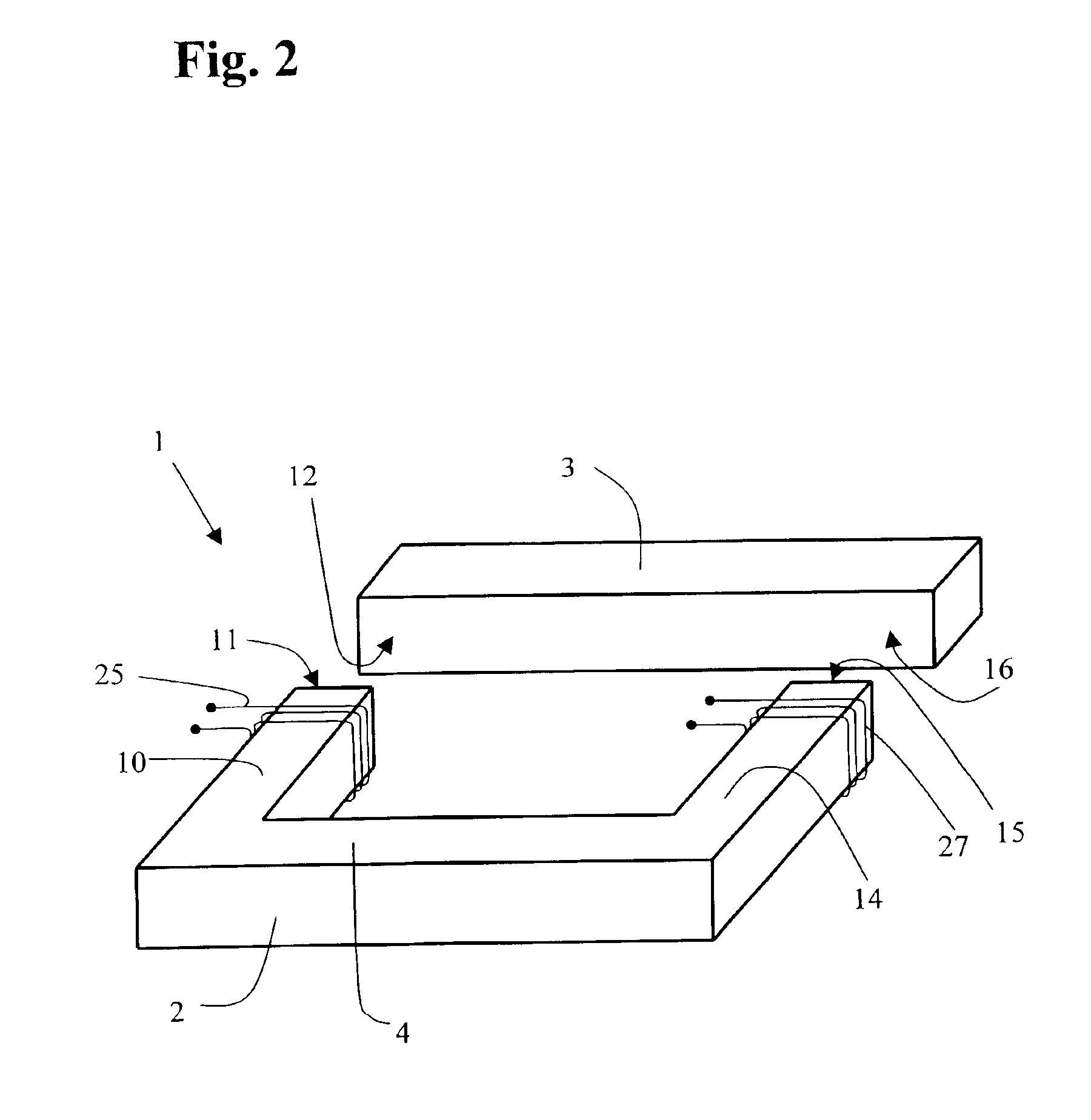
Advantageously the bulk amorphous metal magnetic components are readily assembled to form the one or more magnetic circuits of the finished inductive device. In some aspects, the mating faces of the components are brought into intimate contact to produce a device having low reluctance and a relatively square B-H loop. However, by assembling the device with air gaps interposed between the mating faces, the reluctance is increased, providing a device with enhanced energy storage capacity useful in many inductor applications. The air gaps are optionally filled with non-magnetic spacers. It is a further advantage that a limited number of standardized sizes and shapes of components may be assembled in a number of different ways to provide devices with a wide range of electrical characteristics.
The present device is readily provided with one or more electrical windings. In some embodiments, the windings are wound directly onto one or more of the components. The windings for devices having plural bulk magnetic components are advantageously formed in a separate operation, either in a self-supporting assembly or wound onto a bobbin coil form, and slid onto one or more of the components. The difficulty and complication of providing windings on prior art toroidal magnetic cores is thereby eliminated.

Problems solved by technology

Although many amorphous metals offer superior magnetic performance when compared to other common soft ferromagnetic materials, certain of their physical properties make conventional fabrication techniques difficult or impossible.
However, amorphous metals are thinner and harder than virtually all conventional metallic soft magnetic alloys, so conventional stamping or punching of laminations causes excessive wear on fabrication tools and dies, leading to rapid failure.
The resulting increase in the tooling and manufacturing costs makes fabricating bulk amorphous metal magnetic components using such conventional techniques commercially impractical.
The thinness of amorphous metals also translates into an increased number of laminations needed to form a component with a given cross-section and thickness, further increasing the total cost of an amorphous metal magnetic component.
Machining techniques used for shaping ferrite blocks are also not generally suited for processing amorphous metals.
However, the annealing generally renders the amorphous metal very brittle, further complicating conventional manufacturing processes.
As a result of the aforementioned difficulties, techniques that are widely and readily used to form shaped laminations of silicon steel and other similar metallic sheet-form FeNi- and FeCo-based crystalline materials, have not been found suitable for manufacturing amorphous metal devices and components.
Amorphous metals thus have not been accepted in the marketplace for many devices; this is so, notwithstanding the great potential for improvements in size, weight, and energy efficiency that in principle would be realized from the use of a high induction, low loss material.
However, the stresses inherent in a strip-wound toroidal core give rise to certain problems.
In addition, gapping a wound toroid frequently causes additional problems.
Therefore the actual gap tends to close or open in the respective cases by an unpredictable amount as required to establish a new stress equilibrium.
Therefore, the final gap is generally different from the intended gap, absent corrective measures.
Since the magnetic reluctance of the core is determined largely by the gap, the magnetic properties of finished cores are often difficult to reproduce on a consistent basis in the course of high-volume production.
Furthermore, designers frequently seek flexibility not afforded by a limited selection of standard gapped toroidal core structures.
In addition, the equipment needed to apply windings to a toroidal core is more complicated, expensive, and difficult to operate than comparable winding equipment for laminated cores.
Oftentimes a core of toroidal geometry cannot be used in a high current application, because the heavy gage wire dictated by the rated current cannot be bent to the extent needed in the winding of a toroid.
In addition, toroidal designs have only a single magnetic circuit.
Such a process understandably entails significant manual labor and manipulation steps involving brittle annealed amorphous metal ribbons.
These steps are especially tedious and difficult to accomplish with cores smaller than 10 kVA.
Furthermore, in this configuration, the cores are not readily susceptible to controllable introduction of an air gap, which is needed for many inductor applications.
Another difficulty associated with the use of ferromagnetic amorphous metals arises from the phenomenon of magnetostriction.
As an amorphous metal magnetic device is stressed, the efficiency at which it directs or focuses magnetic flux is reduced, resulting in higher magnetic losses, reduced efficiency, increased heat production, and reduced power.
The extent of this degradation is oftentimes considerable.
Stress levels that would not have a deleterious effect on the magnetic properties of these conventional metals have a severe impact on magnetic properties such as permeability and core loss, which are important for inductive components.
For example, the '649 patent teaches that forming amorphous metal cores by rolling amorphous metal into a coil, with lamination using an epoxy, detrimentally restricts the thermal and magnetic saturation expansion of the coil of material.
High internal stresses and magnetostriction are thereby produced, which reduce the efficiency of a motor or generator incorporating such a core.
However, the increase in frequency also markedly increases the magnetic losses of these components.
The limitations of magnetic components made using existing materials entail substantial and undesirable design compromises.
In many applications, the core losses of the common electrical steels are prohibitive.
Furthermore, the desirable soft magnetic properties of the permalloys are adversely and irreversibly affected by plastic deformation which can occur at relatively low stress levels.
While soft ferrites often have attractively low losses, their low induction values result in impractically large devices for many applications wherein space is an important consideration.
Moreover, the increased size of the core undesirably necessitates a longer electrical winding, so ohmic losses increase.

Method used


Image

  • Bulk laminated amorphous metal inductive device
  • Bulk laminated amorphous metal inductive device
  • Bulk laminated amorphous metal inductive device

Examples


example 1

Preparation and Electro-Magnetic Testing of an Inductive Device Comprising Stamped Amorphous Metal Arcuate Components

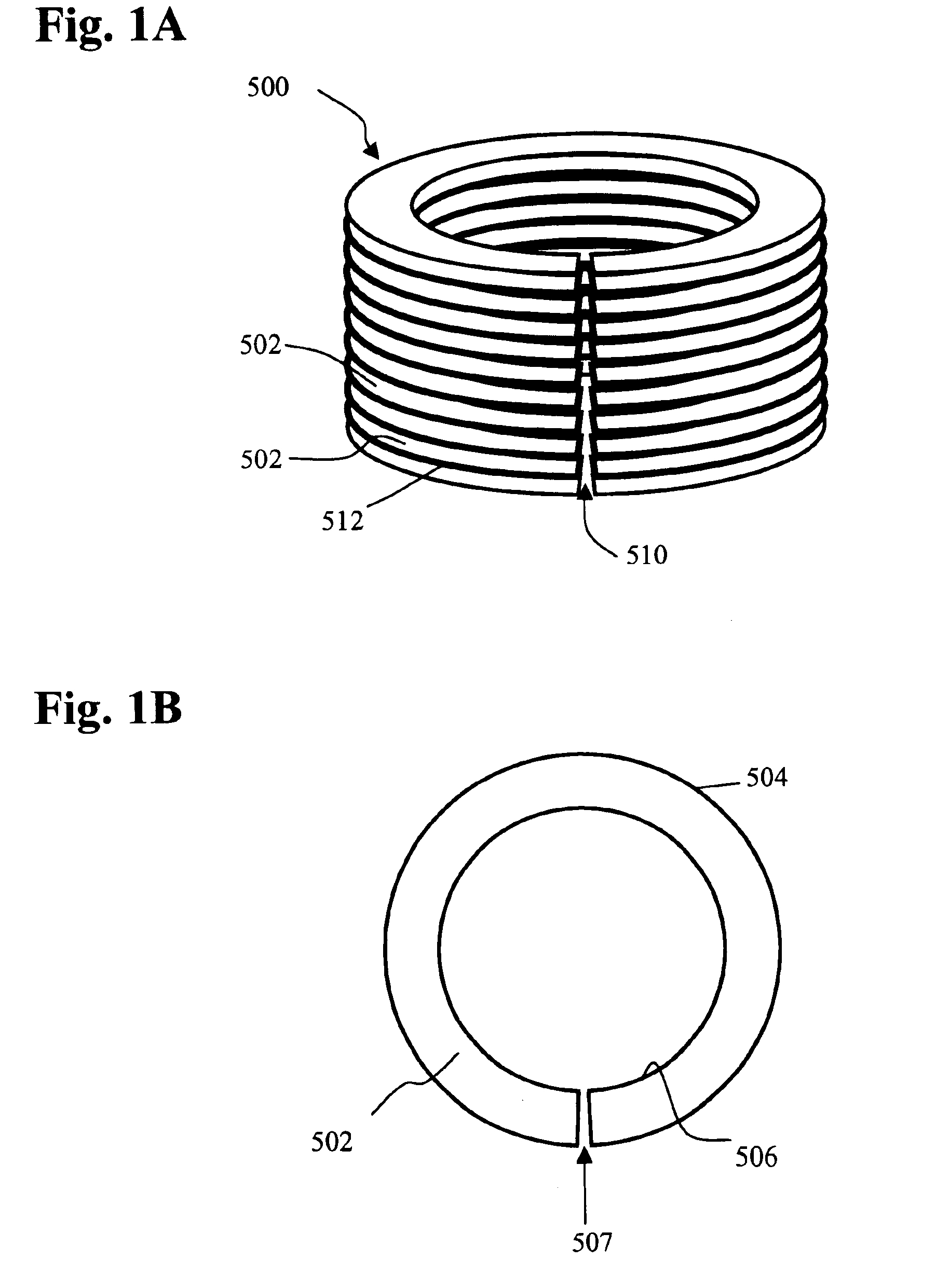
Fe80B11Si9 ferromagnetic amorphous metal ribbon, approximately 60 mm wide and 0.022 mm thick, is stamped to form individual laminations, each having the shape of a 90° segment of an annulus 100 mm in outside diameter and 75 mm in inside diameter. Approximately 500 individual laminations are stacked and registered to form a 90° arcuate segment of a right circular cylinder having a 12.5 mm height, a 100 mm outside diameter, and a 75 mm inside diameter, generally as illustrated by FIG. 12. The cylindrical segment assembly is placed in a fixture and annealed in a nitrogen atmosphere. The anneal consists of: 1) heating the assembly up to 365° C.; 2) holding the temperature at approximately 365° C. for approximately 2 hours; and, 3) cooling the assembly to ambient temperature. The cylindrical segment assembly is removed from the fixture. The cylindrical segment assembly is ...

example 2

High Frequency Electro-Magnetic Testing of an Inductive Device Comprising Stamped Amorphous Metal Arcuate Components

A cylindrical test core comprising four stamped amorphous metal arcuate components is prepared as in Example 1. Primary and secondary electrical windings are fixed to the test assembly. Electrical testing is carried out at 60, 1000, 5000, and 20,000 Hz and at various flux densities. Core loss values are measured and compared to catalogue values for other ferromagnetic materials in similar test configurations (National-Arnold Magnetics, 17030 Muskrat Avenue, Adelanto, Calif. 92301 (1995)). The test data are compiled in Tables 1, 2, 3, and 4 below. As best shown by the data in Tables 3 and 4, the core loss is particularly low at excitation frequencies of 5000 Hz or more. Such low core loss makes the magnetic component of the invention especially well suited for use in constructing inductive devices of the present invention. A cylindrical test core constructed in accordan...

example 3

High Frequency Behavior of an Inductive Device Comprising Stamped Amorphous Metal Arcuate Components

The core loss data of Example 2 above are analyzed using conventional non-linear regression methods. It is determined that the core loss of a low-loss bulk amorphous metal device comprised of components fabricated with Fe80B11Si9 amorphous metal ribbon can be essentially defined by a function having the form

L(Bmax, f)=c1f(Bmax)n+c2fq(Bmax)m

Suitable values of the coefficients c1 and c2 and the exponents n, m, and q are selected to define an upper bound to the magnetic losses of the bulk amorphous metal component. Table 5 recites the losses of the component in Example 2 and the losses predicted by the above formula, each measured in watts per kilogram. The predicted losses as a function of f (Hz) and Bmax (Tesla) are calculated using the coefficients c1=0.0074 and c2=0.000282 and the exponents n=1.3, m=2.4, and q=1.5. The loss of the bulk amorphous metal device of Example 2 is less than...


PUM

PropertyMeasurementUnit
Magnetic fieldaaaaaaaaaa
Frequencyaaaaaaaaaa
Frequencyaaaaaaaaaa

Abstract

A bulk amorphous metal inductive device comprises a magnetic core having at least one low-loss bulk ferromagnetic amorphous metal magnetic component forming a magnetic circuit having an air gap therein. The component comprises a plurality of similarly shaped layers of amorphous metal strips bonded together to form a polyhederally shaped part. The device has one or more electrical windings and is easily customized for specialized magnetic applications, e.g. for use as a transformer or inductor in power conditioning electronic circuitry employing switch-mode circuit topologies and switching frequencies ranging from 1 kHz to 200 kHz or more. The low core losses of the device, e.g. a loss of at most about 12 W / kg when excited at a frequency of 5 kHz to a peak induction level of 0.3 T, make it especially useful at frequencies of 1 kHz or more.

Description

BACKGROUND OF THE INVENTION1. Field of the InventionThis invention relates to an inductive device, and more particularly, to a high efficiency, low core loss inductive device having a core comprising one or more bulk amorphous metal magnetic components.2. Description of the Prior ArtInductive devices are essential components of a wide variety of modern electrical and electronic equipment, most commonly including transformers and inductors. Most of these devices employ a core comprising a soft ferromagnetic material and one or more electrical windings that encircle the core. Inductors generally employ a single winding with two terminals, and serve as filters and energy storage devices. Transformers generally have two or more windings. They transform voltages from one level to at least one other desired level, and electrically isolate different portions of an overall electric circuit. Inductive devices are available in widely varying sizes with correspondingly varying power capacities...

Claims


Application Information

Patent Timeline
IPC IPC(8): H01F3/14H01F27/245H01F3/00H01F41/02H01F3/02
CPCH01F3/14H01F1/15333H01F41/0226H01F27/25H01F3/02H01F27/24H01F41/02
Inventor DECRISTOFARO, NICHOLAS J.FISH, GORDON E.HASEGAWA, RYUSUKEKROGER, CARL E.LINDQUIST, SCOTT M.TATIKOLA, SESHU V.
Owner METGLAS INC
Learn More