
Magnetic toy assembly

a toy assembly and magnet technology, applied in the field of magnet toy assembly, can solve the problems of repulsion between, repulsion force that makes it difficult or does not permit sable reciprocal positioning of single toy pieces, and the result is a greater overall dimension of the toy pieces, and the overall size of the magnets

Active Publication Date: 2016-04-26
VICENTELLI CLAUDIO
View PDF14 Cites 0 Cited by
  • Summary
  • Abstract
  • Description
  • Claims
  • Application Information

AI Technical Summary

Benefits of technology

The present invention provides a magnetic toy assembly with a better magnetic system for anchoring toy pieces. The magnetic system can create bi-dimensional or three-dimensional puzzles and playthings. The magnets in the toys can flow through magnetic circuits, either in series or parallel, to create a magnetic anchorage force that can hold the toys in place without repelling them. This reduces the likelihood of the toys getting stuck together and also allows for a more complex magnetic system that can create more intricate patterns. The cost of the magnetic system is low compared to previous systems.

Problems solved by technology

Such a solution does not enable the magnetomotive anchorage force H of the magnet to be exploited appropriately, inasmuch as the total air closure of the flux generated by the magnet entails a high reluctance, and a consequent reduction of the magnetic anchorage force; to remedy this drawback, in order to obtain the desired magnetic anchorage force of the single toy pieces, magnets of greater dimensions should be used to compensate for the drop of the magnetomotive force caused by the reluctance of the long air path, with consequent greater magnet costs and greater overall dimensions of the toy pieces.
Another drawback of known magnetic anchorage systems consists of the magnetic repulsion between toy pieces if contiguous pieces of the toy have identical magnetic poles N or S similarly oriented.
In fact, if two or more magnets with similarly oriented polarities are placed next to one another, the flux lines that close in air around each magnet interfere with one another, generating repulsion forces that make difficult or do not permit sable reciprocal positioning of the single toy pieces.

Method used


Image

  • Magnetic toy assembly
  • Magnetic toy assembly
  • Magnetic toy assembly

Examples


Embodiment Construction

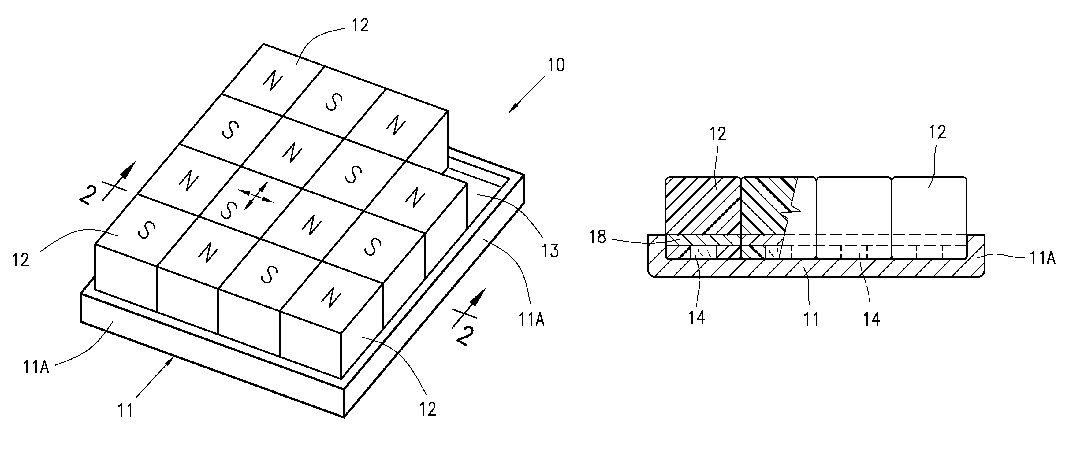
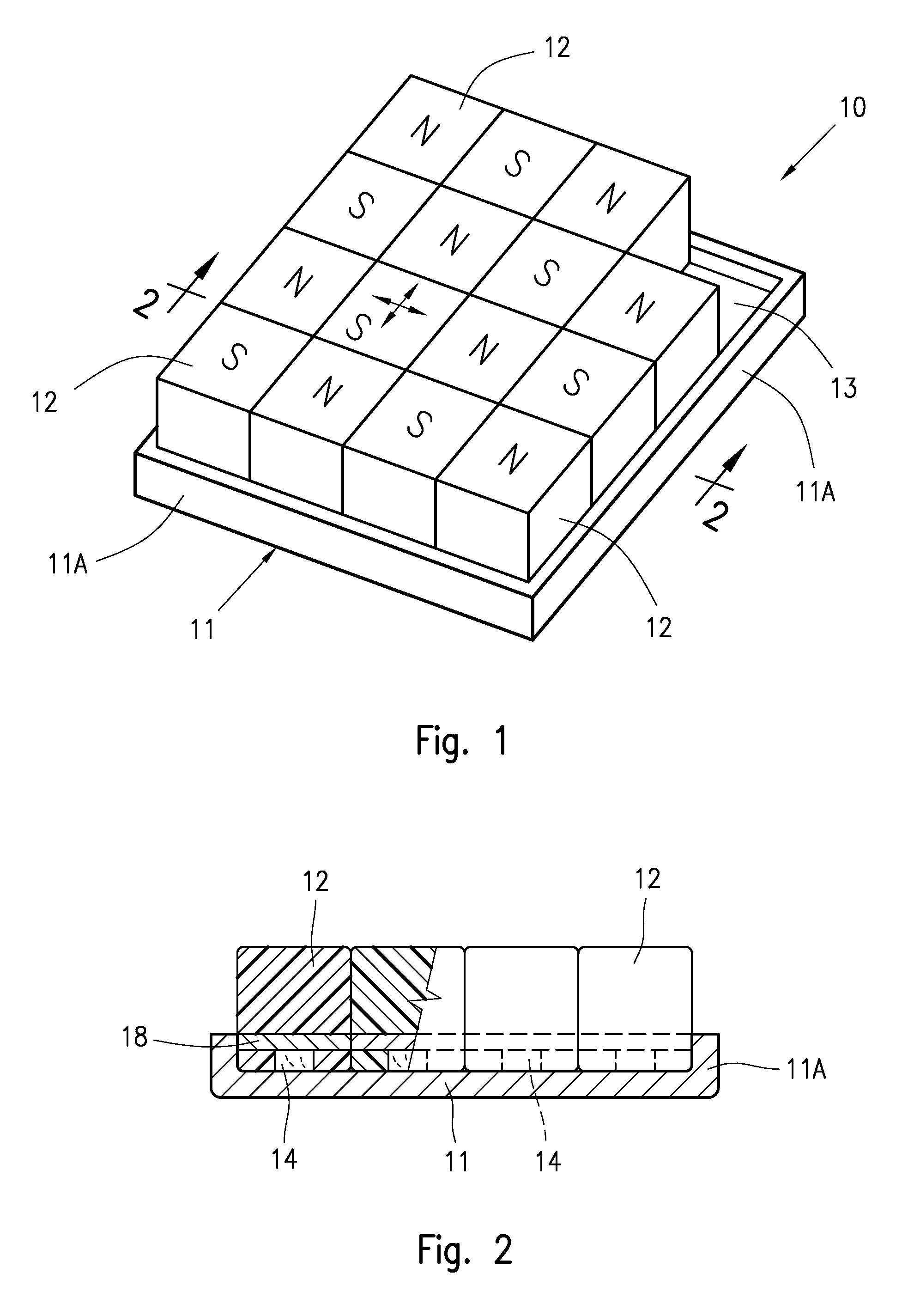
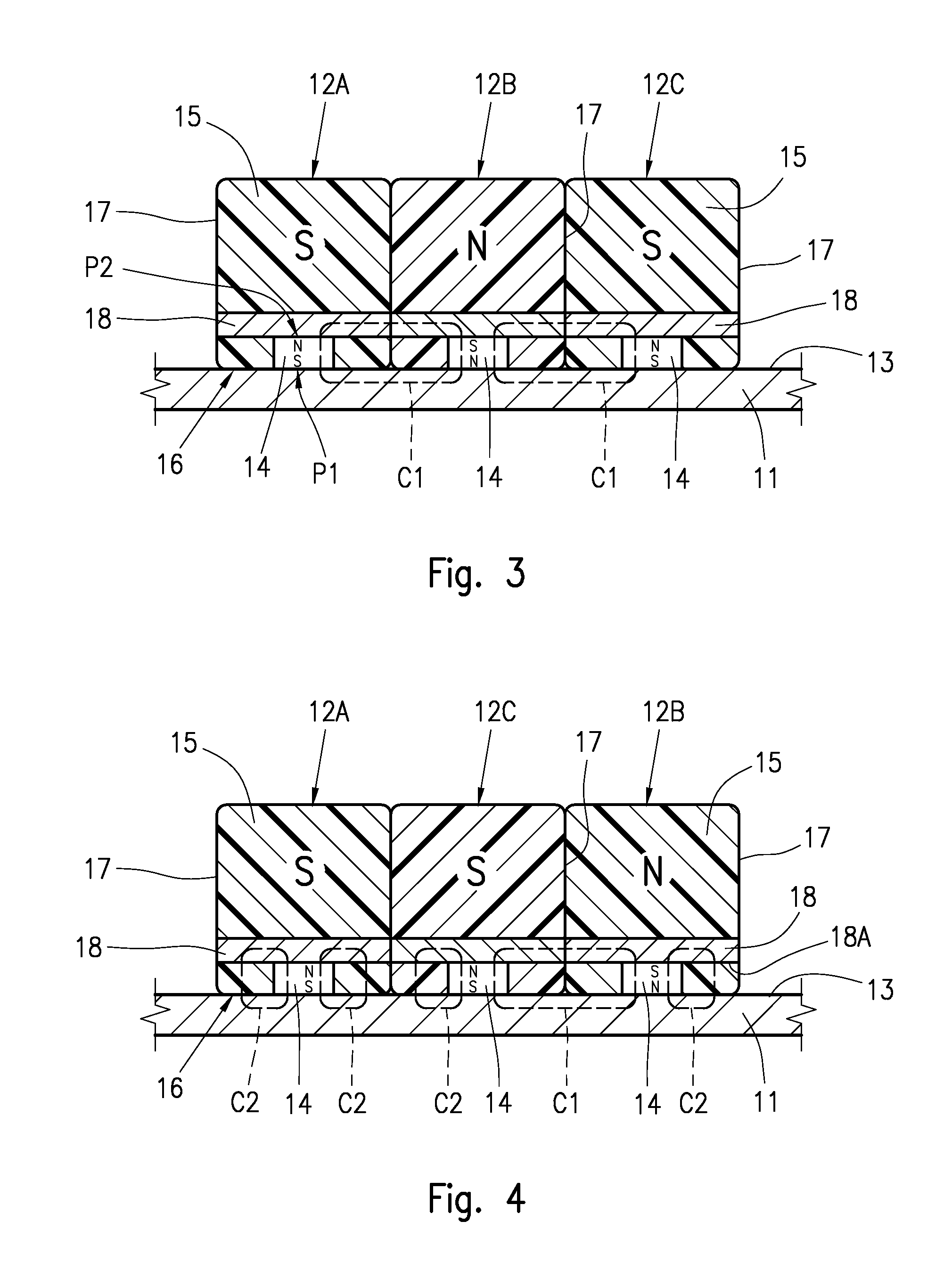
[0055]The general features of the magnetic toy assembly according to the invention will now be disclosed with reference to a bi-dimensional toy assembly shown in the example of FIGS. 1 to 7.

[0056]As shown in FIG. 1, the toy assembly, indicated overall with 10, is in the shape of a bi-dimensional assembly in which the various main toy pieces that make up the puzzle and / or the plaything can be moved in two orthogonal directions, on a slide plane, as schematically shown.

[0057]More precisely, the toy assembly 10 comprises a base member 11 having a planar slide surface 13 and a plurality of main toy pieces 12, which are magnetically anchorable to the slide surface 13 of the base member 11, such that the various toy pieces 12 can be moved singularly and / or by groups, in one or both directions, so as to form a logical sequence or an orderly arrangement of the various toy pieces 12 of the puzzle and / or of the plaything; the slide surface 13 can comprise one or more empty spaces to enable on...


PUM


Abstract

A magnetic toy assembly suitable for puzzles and playthings includes plural main toy pieces that are magnetically anchorable, in a slidable manner, to a slide surface of a bi-dimensional or three-dimensional base member in magnetically conductive material. Each main toy piece includes: a body made of magnetically non-conductive material, having a rear side surface configured to slidably contact the slide surface of the base member; side contact surfaces configured to allow a contact and a relative sliding movement between the main toy pieces; and at least one magnet at the rear side surface for anchoring the main toy piece to the slide surface of the base member. A number of main toy pieces include a pole extension for the magnetic flux.

Description

BACKGROUND OF THE INVENTION[0001]The present invention refers to a magnetic toy assembly suitable for forming bi-dimensional and three-dimensional puzzles and / or playthings, and in particular relates to a magnetic toy assembly comprising a plurality of main toy pieces that are magnetically anchorable, in a slidable manner, to a slide surface of an anchorage base member to be moved, placed alongside and positioned amongst one another to make a puzzle and / or a plaything, in which the various toy pieces have improved features from the point of view of magnetic anchorage force and / or the quantity of magnetic material used to provide the anchorage force.PRIOR ART[0002]Magnetic puzzles or playthings of the type comprising a plurality of main toy pieces, magnetically held together by a bi-dimensional or three-dimensional anchorage base member, are well-known from the prior art.[0003]For example, EP0149326, GB2128104 and GB2196542 show two-dimensional puzzles in which a plurality of single ...

Claims


Application Information

Patent Timeline
Patent Type & Authority Patents(United States)
IPC IPC(8): A63H33/26A63F9/08A63F9/12A63H33/04
CPCA63H33/26A63F9/0807A63F9/0838A63F9/0857A63F2009/124A63F2009/1212A63H33/046
Inventor VICENTELLI, CLAUDIO
Owner VICENTELLI CLAUDIO
Learn More