Supporting structure of optical element, exposure apparatus having the same, and manufacturing method of semiconductor device

a technology of supporting structure and optical element, which is applied in the direction of photomechanical equipment, instruments, printing, etc., can solve the problems of degrading the performance of the optical system, and affecting the aberration of the lens, so as to reduce the deformation of the lens surface, stable high resolution, and small aberration

Inactive Publication Date: 2005-03-15
CANON KK
View PDF20 Cites 52 Cited by
  • Summary
  • Abstract
  • Description
  • Claims
  • Application Information

AI Technical Summary

Benefits of technology

Accordingly, it is an object of the present invention to provide, by solving the conventional problems described above, a supporting structure of optical elements, which can reduce the lens surface deformation due to the strain produced by changes in ambient temperature and during the assembling so as to obtain a stable high resolution with small aberration, an optical apparatus such as an exposure apparatus constructed by using the supporting structure, and a manufacturing method of a semiconductor device, etc., using the apparatus.

Problems solved by technology

However, in the structure of the conventional lens barrel mentioned above, upon changing of ambient temperature, since the lenses and lens barrel elements respectively change in shape, the aberration thereof may change.
In an exposure apparatus especially using a light source with a short wavelength, lenses are made from quartz or fluorite; since materials of the lenses and the lens barrel elements differ in the thermal expansion coefficient from each other, they cannot expand or shrink simply and freely without restriction from outside, respectively; consequently, the lens figure largely changes, thereby such deformation due to temperature changes largely affects the aberration of the lenses.
Plural supporting members 105 are generally overlaid one on another to be arranged in the axial direction; when an external force is applied thereto during the connection thereof by overlaying or due to other reasons, the metallic frame for holding the lens is pressurized so that the lens is subjected to an external force from the screw-rings, etc., thereby deforming the lens figure, resulting in degraded performance of the optical system.
However, in this structure, it is known that upon changes in ambient temperature, the lens surface is deformed due to the thermal expansion coefficient difference between the lens and the metallic frame (when the lens is supported with three-point supporting, the 3θ deformation sensitively changes relative to the temperature), so that the desired optical performance cannot be obtained.

Method used


Image

  • Supporting structure of optical element, exposure apparatus having the same, and manufacturing method of semiconductor device
  • Supporting structure of optical element, exposure apparatus having the same, and manufacturing method of semiconductor device
  • Supporting structure of optical element, exposure apparatus having the same, and manufacturing method of semiconductor device

Examples


embodiment

(Embodiment)

Embodiments according to the present invention will be described below.

first embodiment

(First Embodiment)

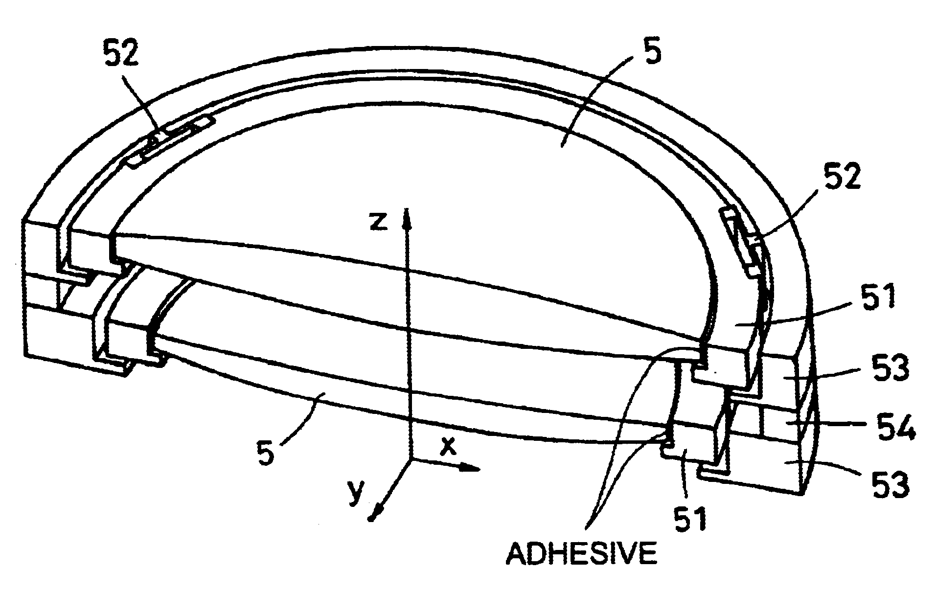
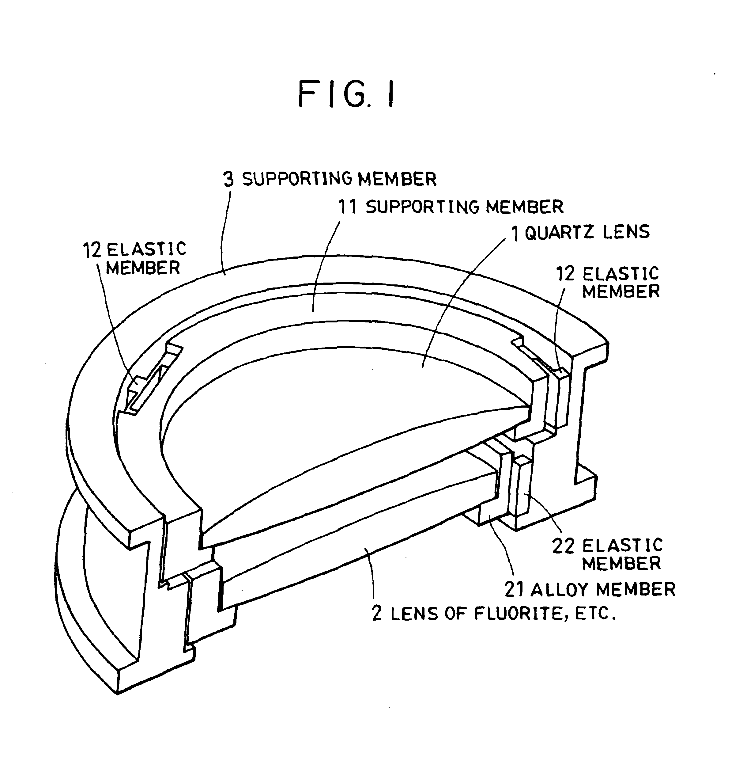
In a first embodiment, a supporting member of a lens is formed by using the above-mentioned structure, and FIG. 1 shows a half of optical elements according to the embodiment.

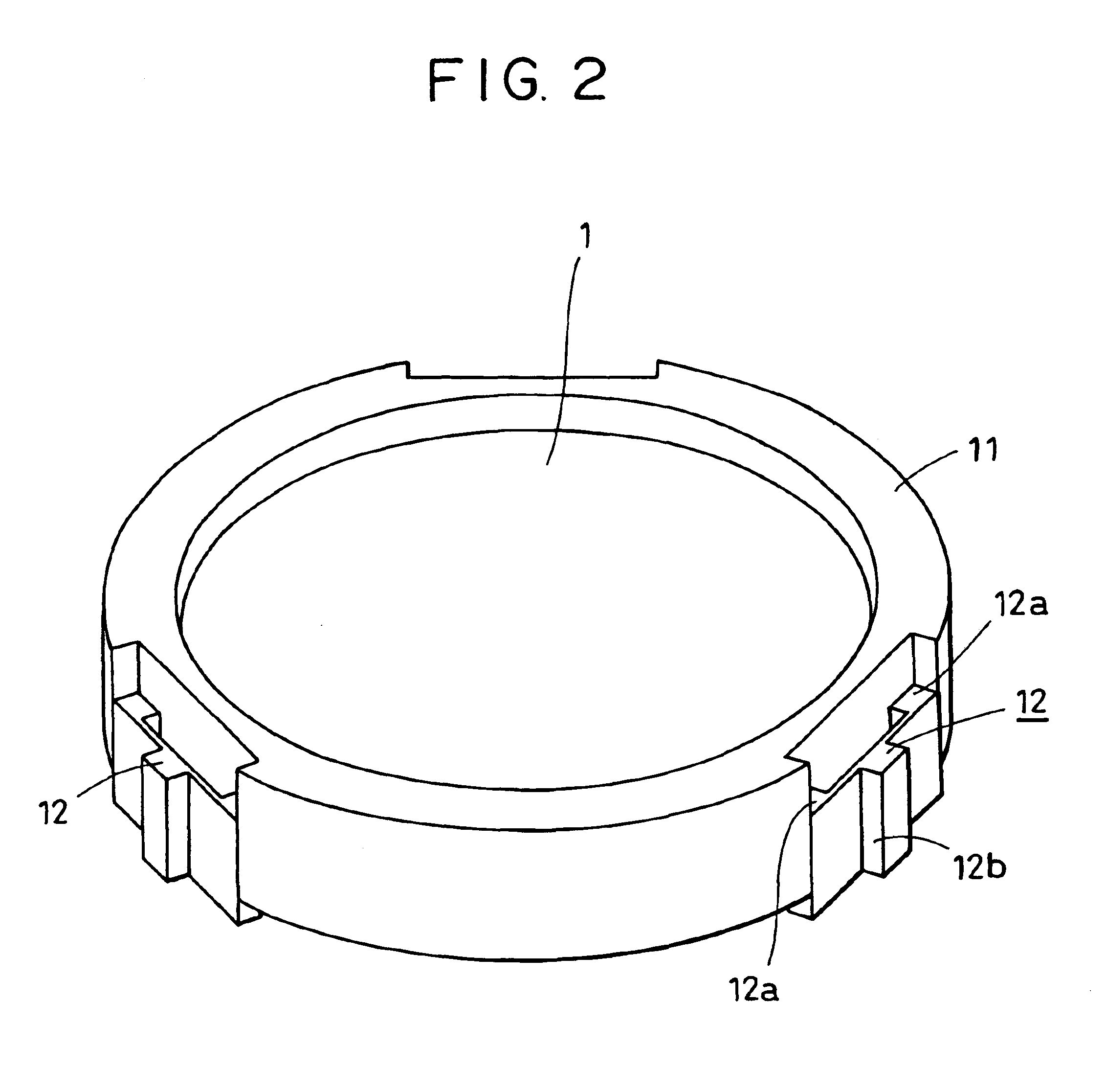
The drawing shows a quartz lens 1 and the lens supporting member 11 made from invar, which is a nickel alloy having a thermal expansion coefficient substantially identical to that of quartz. In addition, the lens 1 is fixed to the supporting member 11 by adhesion.

In the peripheral portions of the supporting member 11, plural cut-outs are formed so as to arrange elastic member 12 therein, which are leaf springs. In the elastic member 1, both plate ends are connected to the supporting member 11 while the center thereof is connected to the supporting member 3. By this supporting structure, the elastic member 12 has small elasticity relative to the optical elements in the radial direction.

The drawing also shows a fluorite lens 2 and a supporting member 21 for supporting the lens 2, which is brass,...

second embodiment

(Second Embodiment)

FIG. 3 illustrates the structure of a lens supporting member according to a second embodiment of the present invention.

The drawing shows a quartz lens 31, a lens supporting member 32 made from invar, a rubber adhesive member 33 having elasticity, and a member 34 for supporting the lens supporting member 32, which is made from iron. In the embodiment, just like the first embodiment, the thermal expansion coefficient of the supporting member 32 is also to be close to that of the lens 31 and the unnecessary thermal deformation due to the thermal expansion coefficient difference between the supporting members 34 and 32 can be relieved by the elasticity of the adhesive 33, enabling the harmful deformation of the lens surface figure to be reduced.


PUM

PropertyMeasurementUnit
wavelengthaaaaaaaaaa
supporting structureaaaaaaaaaa
outer diameteraaaaaaaaaa

Abstract

A supporting structure for supporting an optical element. The supporting structure includes a first supporting member for supporting the optical element, a second supporting member arranged in an outer diameter side of the first supporting member for supporting the first supporting member, and an elastic member placed between the first supporting member and the second supporting member in the radial direction of the optical element. The inner diameter side of the elastic member is connected to the first supporting member while an outer diameter side of the elastic member is connected to the second supporting member. The elastic member is elastically deformable in the radial direction.

Description

BACKGROUND OF THE INVENTION1. Field of the InventionThe present invention relates to a supporting structure of optical elements, an optical apparatus such as an exposure apparatus constructed by using the supporting structure, and a method for manufacturing a semiconductor device by using the optical apparatus, etc., and in particular relates to a supporting member for supporting an optical element such as a lens and a mirror, and an optical apparatus with a high degree of accuracy which comprises the supporting member for supporting the optical element, the optical apparatus being an exposure apparatus for use in manufacturing semiconductor integrated circuits, for example.2. Description of the Related ArtA semiconductor exposure apparatus is an apparatus for transferring a negative plate (reticle) having a circuit pattern onto a substrate (silicon wafer). During the transferring, a projection lens is used for forming an image of the reticle pattern on the wafer, and high resolutio...

Claims


Application Information

Patent Timeline
Patent Type & Authority Patents(United States)
IPC IPC(8): G03F7/20H01L21/027G02B7/02
CPCG03F7/70825G02B7/028G03F7/70891
Inventor EBINUMA, RYUICHISUDO, YUJI
Owner CANON KK
Why Eureka
Try Eureka