
Magnetic tunneling junction and fabrication method thereof

a technology fabrication method, which is applied in the field of magnetic tunneling junction, can solve the problems of repeated interference of cells, magnetic creep phenomenon, and complicating magnetic switching behavior, and achieve the effect of improving the tmr ratio

Inactive Publication Date: 2005-02-01
KOREA INST OF SCI & TECH
View PDF6 Cites 29 Cited by
  • Summary
  • Abstract
  • Description
  • Claims
  • Application Information

AI Technical Summary

Benefits of technology

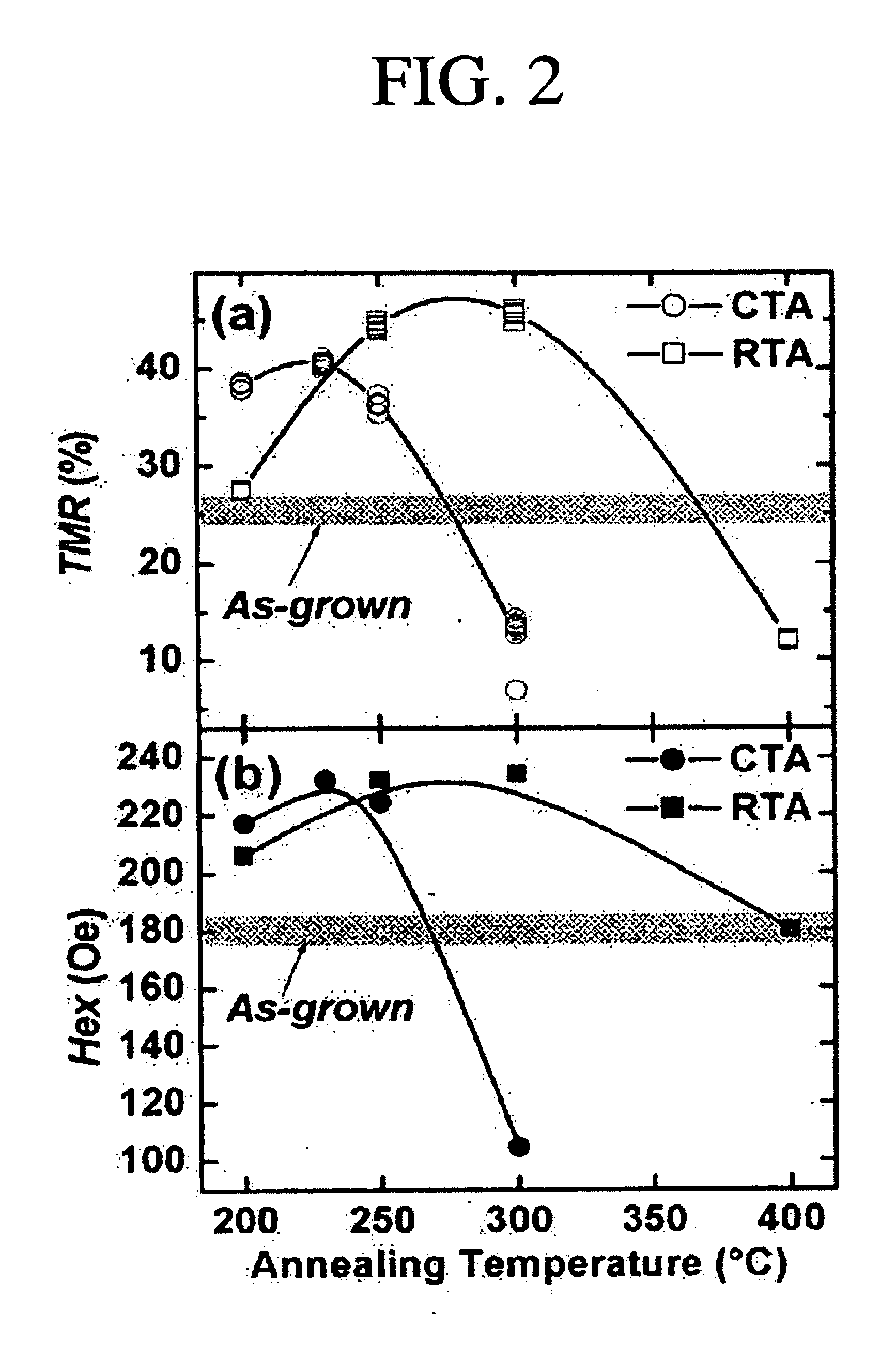
Therefore, an object of the present invention is to improve a TMR ratio and an exchanging magnetic anisotropy (Hex) of a magnetic tunnel function device only by a thermal treatment for a short time.
Another object of the present invention is to improve squareness in a magnetic switching of a free layer.
Still another object of the present invention is to improve a thermal stability of a magnetic tunnel junction.

Problems solved by technology

In the MRAM operation, since, in most cases, one cell is selected by one of a bit line or a word line, the cells are repeatedly interfered.
Thus, there is a high possibility that a magnetic creep phenomenon occurs so that a magnetization is made half or a magnetic switching is completely made.
In such a case, an error occurs in the memory device, so that it is necessary to strongly fix the magnetization by the anti-ferromagnetic layer.
The main reason for this is estimated to be a complicate magnetic switching behavior due to complicate magnetic domains and an unevenness of an infinitesimally patterned cell that is fabricated by an etching process.

Method used


Image

  • Magnetic tunneling junction and fabrication method thereof
  • Magnetic tunneling junction and fabrication method thereof
  • Magnetic tunneling junction and fabrication method thereof

Examples


Embodiment Construction

Reference will now be made in detail to the preferred embodiments of the present invention, examples of which are illustrated in the accompanying drawings.

Compared with the conventional art, the present invention accomplishes an economic effect by considerably reducing time taken for a thermal treatment and a cooling time, and improved electromagnetic characteristics and thermal stability.

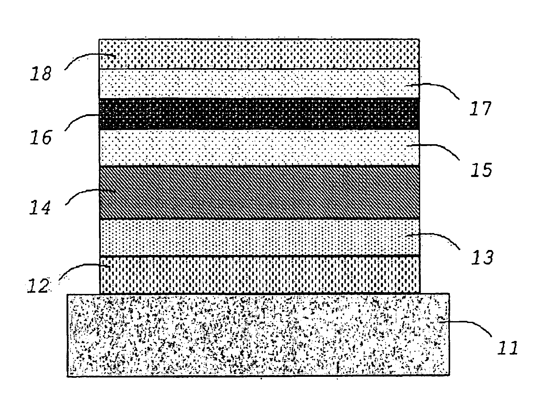
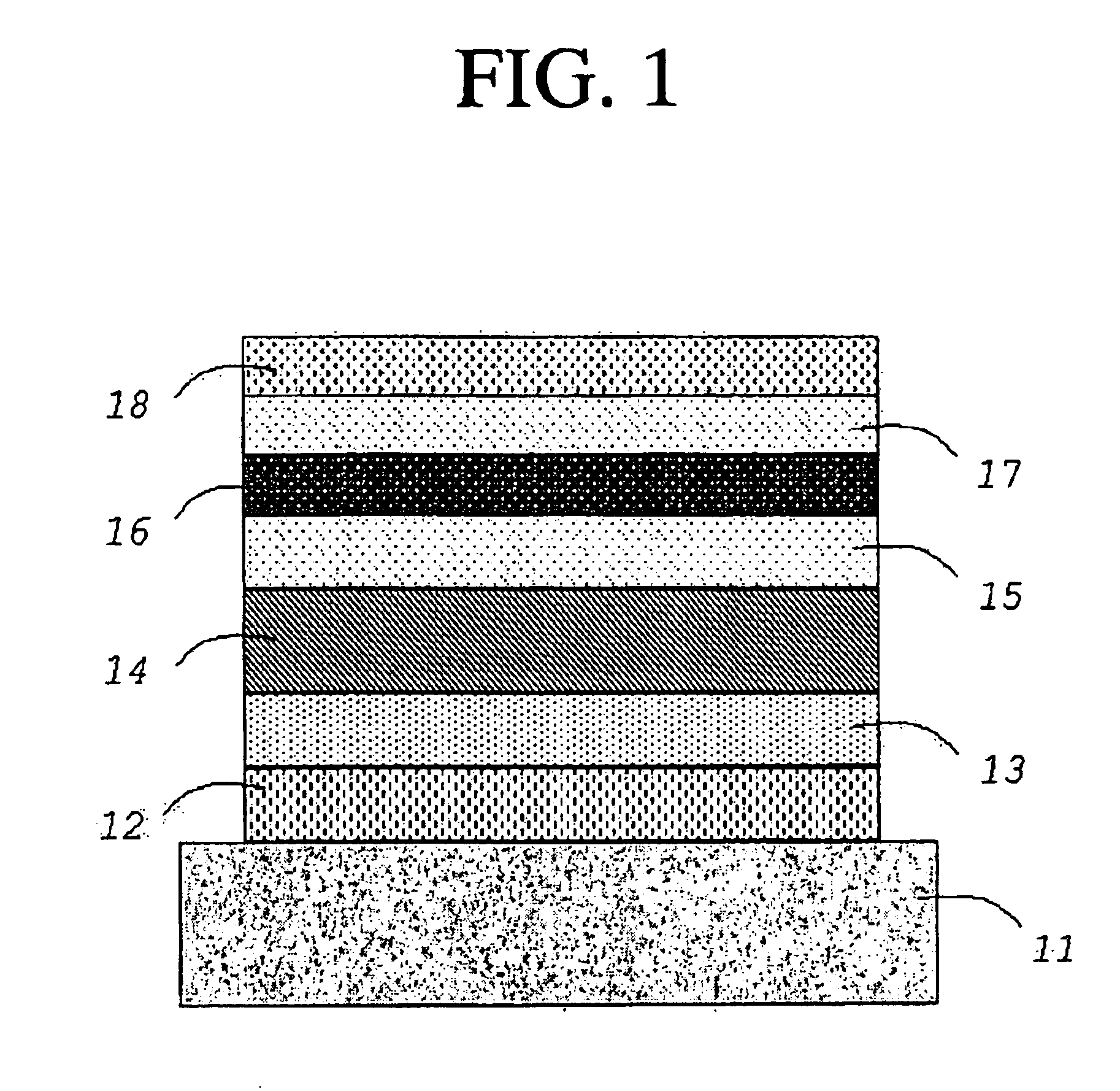
A magnetic tunnel junction fabricated by the present invention can have an exchange bias type, in which a first magnetic layer is a pinned layer, a second magnetic layer is a free layer, and an anti-ferromagnetic layer, a pinning layer for pinning a spin direction of the first magnetic layer, is formed at the other side of the first magnetic layer. The first and the second magnetic layers can have a pseudo spin-valve type with different coercive forces to control the spin direction.

The rapid thermal annealing adopted in the present invention is the radial thermal treatment using the infrared lamp, ...


PUM

PropertyMeasurementUnit
Temperatureaaaaaaaaaa

Abstract

A fabrication method of a magnetic tunnel junction includes the steps of: forming a magnetic tunnel junction constructed having a first magnetic layer, a tunnel barrier formed at an upper surface of the first magnetic layer and a second magnetic layer formed at an upper surface of the tunnel barrier; and thermally treating the junction rapidly for 5 seconds˜10 minutes at a temperature of 200˜600° C. to re-distribute oxygens in the tunnel barrier and make the interface between the tunnel barrier and the magnetic layer to be even. The tunneling magnetoresistance and thermal stability of the magnetic tunnel junction can be improved through the rapid thermal annealing.

Description

BACKGROUND OF THE INVENTION1. Field of the InventionThe present invention relates to a magnetic tunneling junction and its fabrication method, and more particularly, to a magnetic tunneling junction with improved electro-magnetic characteristics and thermal stability through a rapid thermal annealing.2. Description of the Background ArtA core technology of a magnetic tunnel junction (MTJ) is a development technology of a thin film material assuming excellent and stable magnetic resistance characteristics and an integrated process technology using the conventional semiconductor circuit and process.Tunneling magnetoresistance (TMR), that is receiving an active study, refers to a phenomenon that a tunneling current differs according to a relative magnetization direction of a ferromagnetic material in a junction with a structure of a ferromagnetic material / insulation material / ferromagnetic material structure.The magnetic resistance thin film assuming the tunnel magnetic resistance, that...

Claims


Application Information

Patent Timeline
IPC IPC(8): H01F41/30H01F41/14H01L43/00H01L43/12G11B5/39H10N50/01H10N50/10
CPCB82Y25/00B82Y40/00H01L43/12H01F41/307Y10T29/49044H10N50/01G11B5/39
Inventor SHIN, KYUNG-HOLEE, WOO-YOUNGPARK, YOUNG-JOONLEE, KYUNG-ILHA, JAE-GEUN
Owner KOREA INST OF SCI & TECH
Learn More