Process of removing a ceramic coating deposit in a surface hole of a component

Active Publication Date: 2005-01-25
GENERAL ELECTRIC CO
View PDF7 Cites 24 Cited by
  • Summary
  • Abstract
  • Description
  • Claims
  • Application Information

AI Technical Summary

Benefits of technology

According to the present invention, there is provided a process of removing ceramic deposits from a surface hole in a component, a particular example being portions of a ceramic coating material deposited on a surface of an air-cooled gas turbine engine component. The process is particularly effective in removing a TBC material deposited in a cooling hole of a component as a result of coating a surface of the component with the TBC material, in which the deposit is removed from the cooling hole without damaging the cooling hole or the TBC surrounding the cooling hole on the coated surface of the component.
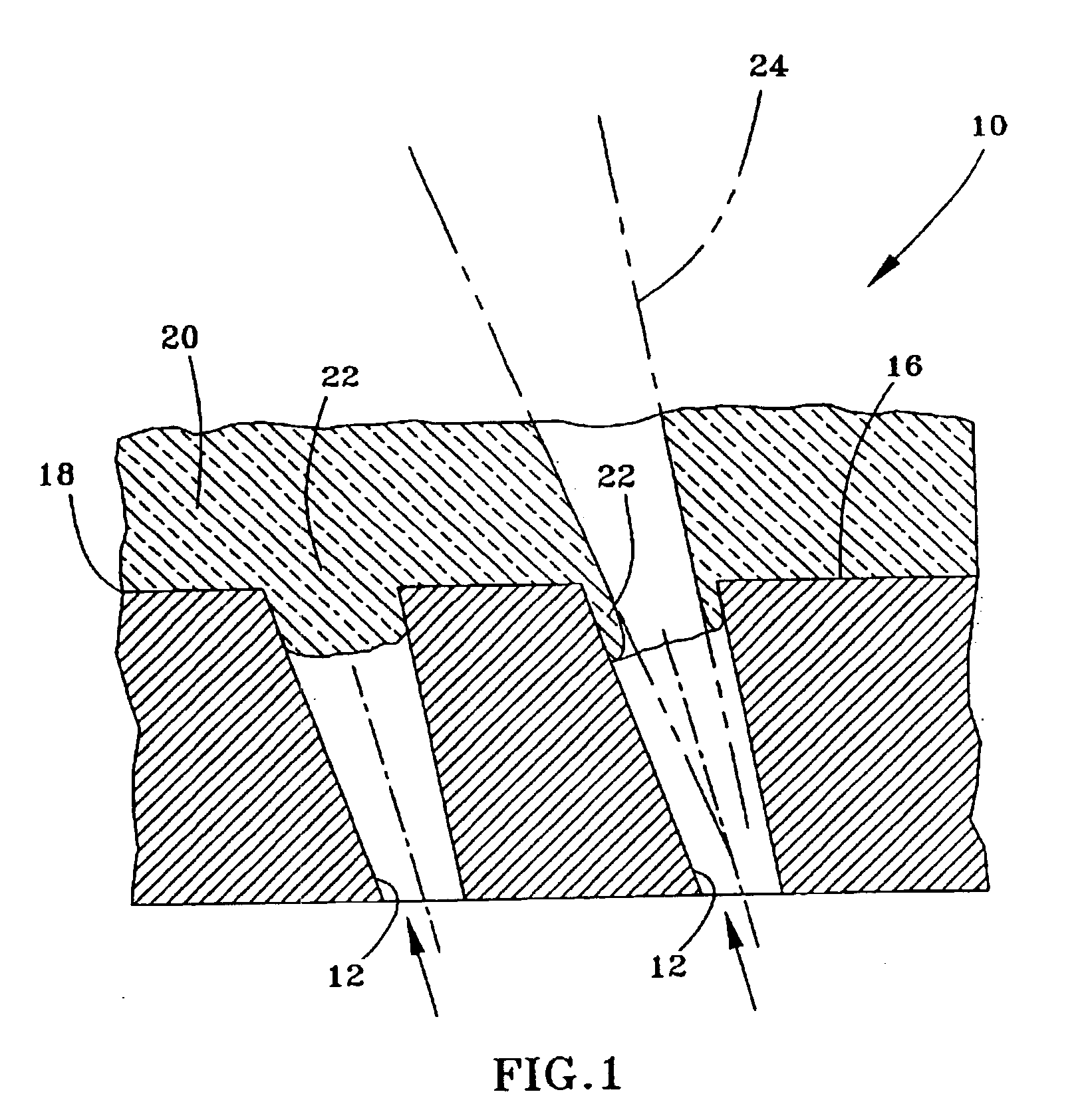
The process of this invention makes use of a pulsed Nd:YAG laser operated with parameters that enable the laser beam to remove ceramic material from a cooling hole without delaminating, cracking or otherwise damaging the TBC surrounding the cooling hole, and without any special equipment or efforts to precisely identify the hole location. Instead, the present invention is able to make use of the same fixturing and programming used to originally install the cooling holes. To enable the use of more relaxed positioning requirements, the pulsed Nd:YAG laser is operated in a free-running mode at relatively lower power levels and higher frequencies that conventionally used. These parameters include a pulse frequency of about 2 to about 20 Hz and pulse widths of about 0.25 to about 6.0 milliseconds, with preferred parameters being dependent on the hole diameter. In addition, the invention makes use of a laser beam whose diameter is smaller than the cooling hole being redrilled, and the laser is equipped with breakthrough detection so that the beam is not projected onto the hole walls, with the result that the hole entrance after laser drilling is defined by remaining ceramic deposits surrounding the hole and is therefore smaller than the original diameter of the hole at the component surface. The process of this invention is able to remove ceramic from cooling holes with diameters of less than 0.020 (about 0.5 mm) and even below 0.010 inch (about 0.25 mm), and even where the TBC surrounding the hole has a thickness in excess of 0.020 (about 0.5 mm).
In view of the above, a process for removing a ceramic deposit from a surface hole in accordance with this invention includes positioning an Nd:YAG laser generator so that a laser beam generated by the generator is directed at the original programmed location of the hole used during installation of the hole. A pulsed laser beam having a diameter less than the as-installed hole is then directed at the programmed location of the hole to remove the ceramic deposit. The pulsed laser beam has a pulse width and pulse frequency that enables the ceramic deposit to be removed from the hole without substantial delamination or cracking of the ceramic coating surrounding the hole. Because special equipment and efforts are not required to precisely identify the hole location, the process of this invention can be easily implemented while also enabling cooling holes to be redrilled with significantly lower manufacturing costs due to reduced cycle time.

Problems solved by technology

However, EDM cannot be used to form cooling holes in a component having an existing ceramic TBC since ceramic is electrically nonconducting.
While laser drilling techniques are capable of forming cooling holes in a TBC-coated component, the brittle ceramic TBC surrounding the cooling hole is prone to delamination and cracking of the TBC at the interface between the TBC and the underlying metallic bond coat.
However, the presence of TBC deposits in the cooling holes of an air-cooled component can detrimentally affect the service life of the component as a result of the TBC altering the shape and reducing the size of the cooling hole openings.
The obstruction of cooling holes with TBC not only occurs with new manufactured air-cooled components, but also when refurbishing a TBC on a component returned from the field.
From the above, it can be seen that manufacturing and refurbishing an air-cooled component protected by a TBC is complicated by the requirement that the cooling holes remain appropriately sized and shaped.
Emer does not disclose modifying a pulsed IR laser beam to avoid the delamination and cracking of the TBC that has been reported by others in the prior art.

Method used


Image

  • Process of removing a ceramic coating deposit in a surface hole of a component
  • Process of removing a ceramic coating deposit in a surface hole of a component

Examples


Embodiment Construction

FIG. 1 represents a cross-sectional view through cooling holes 12 that intersect a surface 16 of an air-cooled component 10 of a gas turbine engine. The component 10 may be formed of an iron, nickel or cobalt-base superalloy, though other high temperature materials could foreseeably be used. As known in the art, to minimize the service temperature of the component 10, heat is transferred from the component 10 by forcing bleed air through the cooling holes 12 in a direction indicated by the arrows in FIG. 1. The amount of heat transferred to the surface 16 of the component 10 can be further reduced by forming the cooling holes 12 to be disposed at an acute angle relative to the surface 16 of the component 10, so that air discharged from the cooling hole 12 flows over the surface 16 of the component 12. Suitable techniques for forming the holes 12 include EDM or laser drilling, though it is foreseeable that the holes 12 could be formed by such other methods as casting or abrasive wate...


PUM

PropertyMeasurementUnit
Temperatureaaaaaaaaaa
Timeaaaaaaaaaa

Abstract

A process of removing ceramic deposits from a surface hole in a component, a particular example being portions of a ceramic coating deposited on a surface of a component equipped with cooling holes. The process makes use of a pulsed Nd:YAG laser operated with parameters that avoid delamination, cracking or otherwise damaging a ceramic coating surrounding a cooling hole. The laser is operated to generate a laser beam that removes some of the ceramic deposit from the hole while a residual portion of the ceramic deposit remains surrounding the hole to define a surface opening.

Description

BACKGROUND OF INVENTION1. Field of the InventionThe present invention generally relates to ceramic coatings deposited on components with surface holes that are required to remain open after the coating process. More particularly, this invention is directed to a method of removing ceramic coating deposits from surface holes using a laser drilling technique having parameters that reduce the incidence of delamination and cracking of the ceramic coating surrounding the surface hole.2. Description of the Related ArtComponents located in certain sections of gas turbine engines, such as the turbine, combustor and augmentor, are often thermally insulated with a ceramic layer in order to reduce their service temperatures, which allows the engine to operate more efficiently at higher temperatures. These coatings, often referred to as thermal barrier coatings (TBC), must have low thermal conductivity, strongly adhere to the article, and remain adherent throughout many heating and cooling cycle...

Claims


Application Information

Patent Timeline
IPC IPC(8): B23K26/00B23K26/38F01D5/28F01D9/02F01D25/00F02C7/00F23R3/42
CPCB23K26/063B23K26/381B23K26/388B23K26/4095B23K26/4005B23K26/401B23K26/408B23P2700/06B23K26/0622B23K26/382B23K26/40B23K26/389B23K2101/001B23K2101/34B23K2103/50B23K2103/52
Inventor DAS, NRIPENDRA NATHBAILEY, MARK SAMUELASH, CLARENCE ALBERTTOMLINSON, THOMAS JOHN
Owner GENERAL ELECTRIC CO
Why Eureka
Try Eureka