
Method and apparatus for heating a zone of an elongate tubular article

Inactive Publication Date: 2005-01-25
SHAWCOR LTD
View PDF18 Cites 3 Cited by
  • Summary
  • Abstract
  • Description
  • Claims
  • Application Information

AI Technical Summary

Benefits of technology

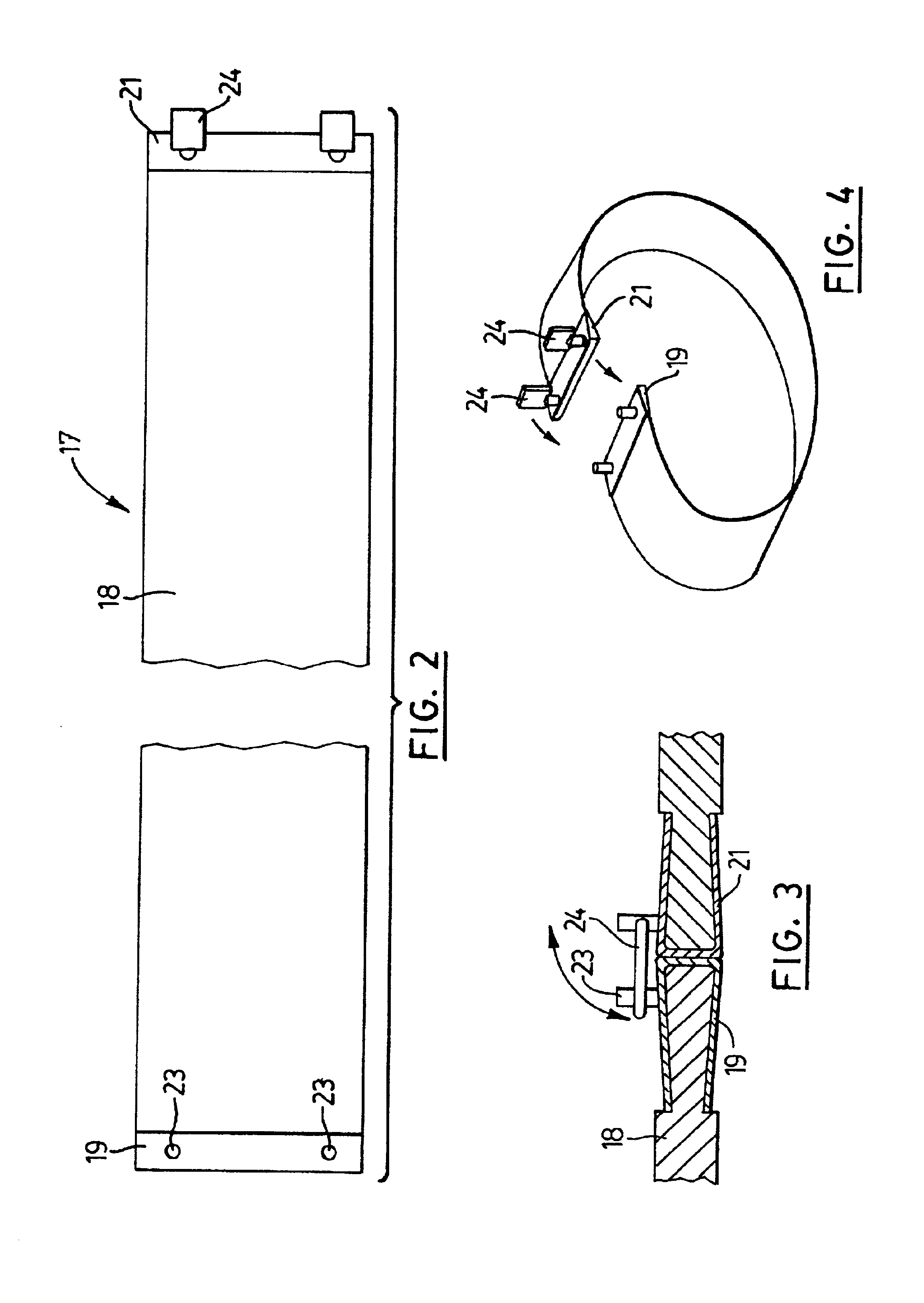
Further, the shroud material serves to reduce the rate of heat transfer through the pipeline coating to the steel pipe, as compared with the rate of heat transfer that would occur if the hot gas source were played directly on the pipeline coating. Such reduction in the rate of heat transfer may for example be achieved by virtue of the fact that the shroud material may be heat insulative, so that a temperature gradient exists between the outer and the inner sides of the shroud material. Secondly, or alternatively, the shroud material may be heat dispersive, that is to say it disperses hot gases transversely over its outer side when a source of hot gas is played on the outer side of the shroud material.
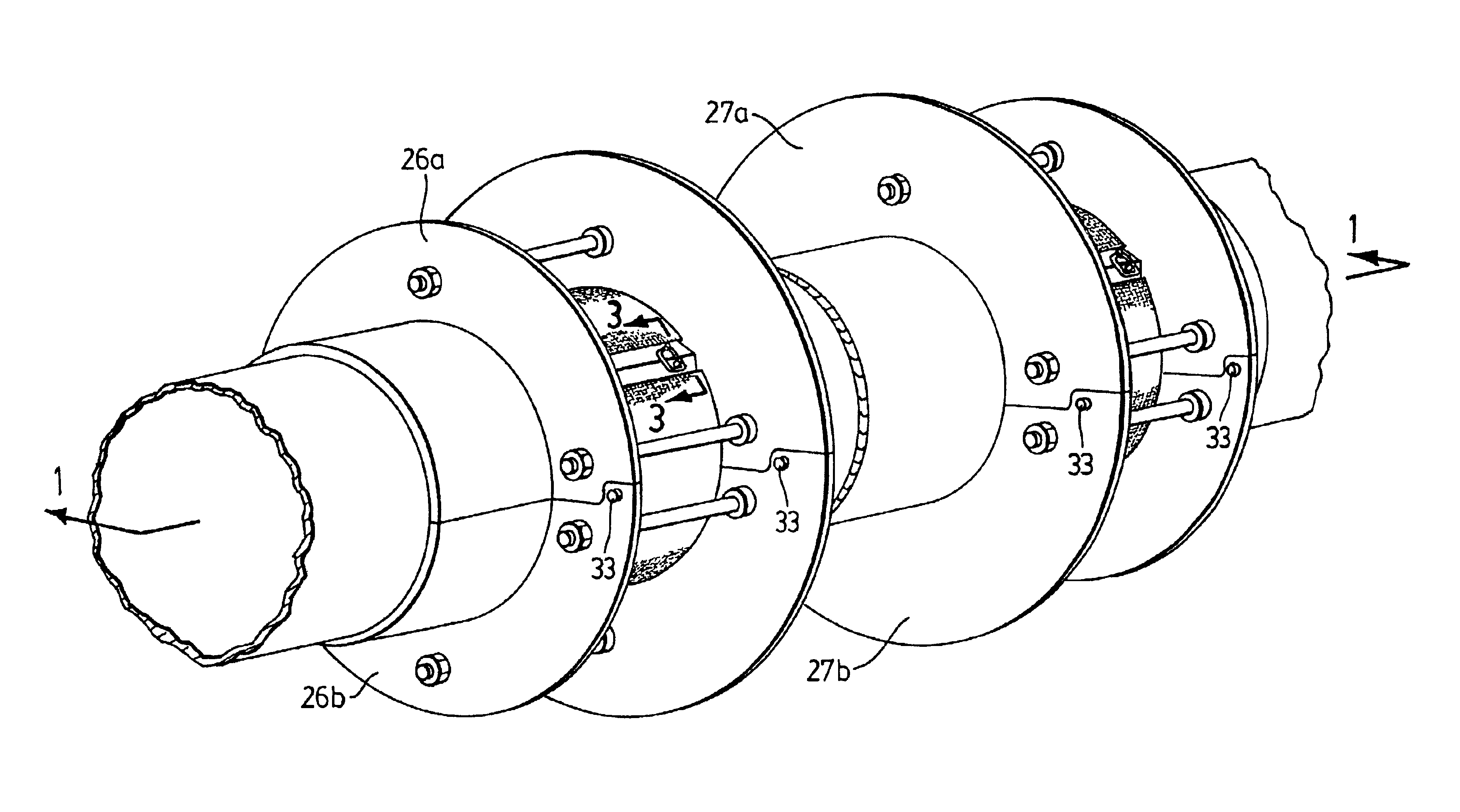
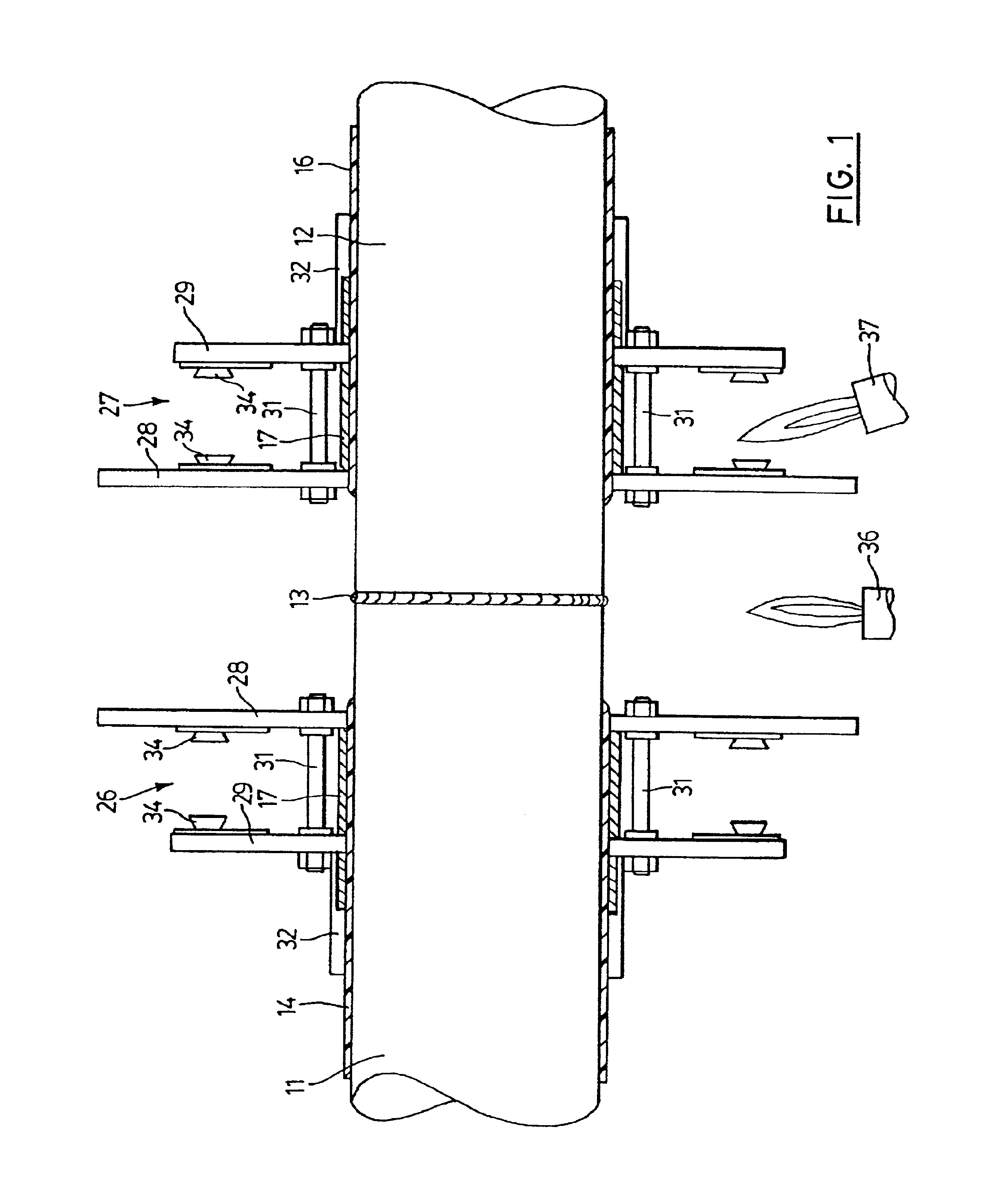
In the preferred form, each heat shield structure consists of an inner split metal flange and an outer split metal flange that are connected together to create a confined space somewhat wider than the width of the portion of the pipeline coating to be heated. The outer flange preferably has a cylindrical axially outward extension to protect the pipeline coating, to assist in securing the shroud material, and to assist in achieving and maintaining alignment with the pipe.

Problems solved by technology

In the absence of the shroud material, the extreme temperature of the flame or hot gas has been found to degrade the pipeline coating.
For example, if the pipeline coating is polypropylene, it causes the surface to become “waxy” due to degradation of the polymer and / or blooming to the surface of lower molecular weight polymer and additives.
Such a surface is very difficult to bond to.

Method used


Image

  • Method and apparatus for heating a zone of an elongate tubular article
  • Method and apparatus for heating a zone of an elongate tubular article
  • Method and apparatus for heating a zone of an elongate tubular article

Examples


example

A pipeline had a coating of 2.5 mm thick 3-layer polypropylene, and the bare steel weld joint was 100 mm wide. The procedure was as follows:

The coating adjacent to both ends of a bare steel weld joint was tightly wrapped with a double wrap of 100 mm wide Siltemp P4CSR.

A heat shield structure as shown in FIGS. 1 to 5 of the accompanying drawings was clamped over each Siltemp blanket.

The steel pipe between the two inner flanges was heated with propane hand held torches to approximately 200° C.

The propane hand torches were then directed between the inner and outer flanges on either end, directing the flame directly at the blanket, until the pipeline coating temperature reached 150 to 1600° C.

The heat shield structures and blankets were removed and immediately thereafter a heat shrink sleeve consisting of a crosslinked polypropylene-based heat shrinkable backing coated inside with a polypropylene based hot melt adhesive was placed over the heated area.

The heat shrink sleeve was shrunk t...


PUM

PropertyMeasurementUnit
Temperatureaaaaaaaaaa
Electrical resistanceaaaaaaaaaa
Flexibilityaaaaaaaaaa

Abstract

A method for heating a zone of an elongate tubular article. A heat resistant, heat transmitting and heat dispersive shroud material is applied to the zone and a hot gas source is applied to the outside of the shroud material to cause heat to be transmitted through the shroud material to the zone.

Description

BACKGROUND OF THE INVENTIONThe present invention relates to a method and apparatus for heating a zone of an elongate tubular article, for example a zone of the surface of a pipeline in the course of applying a sleeve or patch on coated pipes, employing a hot gas source, such as a heater device that provides a heated air stream, or when using a flame, such as a torch flame to heat the pipe.Heating may, for example, be employed for heating a pipeline weld joint and the adjacent coating in the field to a temperature suitable for subsequent installation of a covering. In particular, the present method and apparatus are especially useful where the temperature to which the line coating must be heated exceeds its melting point, and the covering is to be applied is a heat shrinkable sleeve, tape or patch coated with a hot melt adhesive whose adhesive requires the substrate to be heated to a temperature close to or above the melting point of the substrate. More particularly, the method is es...

Claims


Application Information

Patent Timeline
IPC IPC(8): B29B13/02B29B13/00B29C63/00B29C35/04B29C73/34B29C73/00
CPCB29B13/024B29C63/0069B29C35/045B29C73/34B29K2995/0049B29K2023/12B29K2105/128B29K2995/0016B29K2023/00
Inventor BROWN, ROBERT J.BECHTOLD, THOMAS H.
Owner SHAWCOR LTD
Learn More