
Solar/heat shield for pedestal housings used with active electronic devices and/or heat sensitive components

Active Publication Date: 2019-06-06
CHANNELL COMML CORP
View PDF24 Cites 1 Cited by
  • Summary
  • Abstract
  • Description
  • Claims
  • Application Information

AI Technical Summary

Benefits of technology

[0005]The pedestal housing of the present invention provides heat reduction by reducing the solar and radiant heat load on the pedestal. This is accomplished by one or more related methods singularly or combined which include electromagnetic radiation, especially infrared (IR), reflection away from protected components within the pedestal housing; electromagnetic radiation, especially infrared (IR), absorption between the source and the components being shielded; enhanced insulation to reduce heat transfer rates to the protected components; use of the attic as an integral component of a heat/solar shield; and use of a heat/solar shield between the attic and the cover of the pedestal housing. The attic is designed to allow natural convection from the pedestal housing and allow for the use of fans. The attic may also incorporate features to assist in airflow of natural or forced convection such as airflow direction to side vents, and may also be used to hold additional insulation material in place.
[0006]Advantages of the present invention include using an attic to reduce solar heat transfer as well as radiant heat from nearby objects such as rocks, buildings or masonry walls; use of integrated fan attachment points for forced convective cooling in non-metallic pedestal covers; improved insulation in the attic to reduce heat transfer from the attic surface exposed to the sun by improved “R” values; using thinner insulation higher in the attic to reduce heat transfer while retaining room for venting the top of the pedestal housing under the attic and allow for fan use if required; raising the attic further above the top of the cover of the pedestal housing to allow for better heat escape from the pedestal housing; use of an inner layer of h

Problems solved by technology

The increase in the internal temperature of the housing transfers heat to the electronic components with adverse consequences.
These components tend to fail at shorter and shorter intervals with increases in temperature or operate at reduced rates.
As communications companies increase data rates to customers, more active electronics are placed in the outside infrastructure and the higher data rates typically require active components that generate more heat and are more prone to temperature induced failures.
Over the last several years

Method used


Image

  • Solar/heat shield for pedestal housings used with active electronic devices and/or heat sensitive components
  • Solar/heat shield for pedestal housings used with active electronic devices and/or heat sensitive components
  • Solar/heat shield for pedestal housings used with active electronic devices and/or heat sensitive components

Examples


Example

DETAILED DESCRIPTION OF THE DRAWINGS

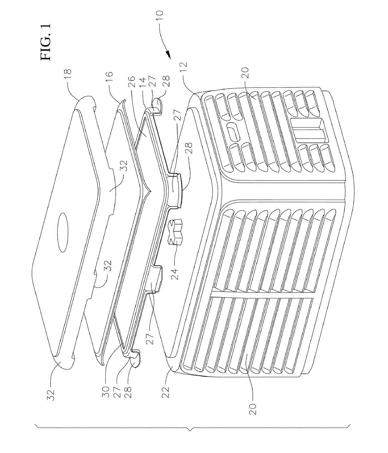
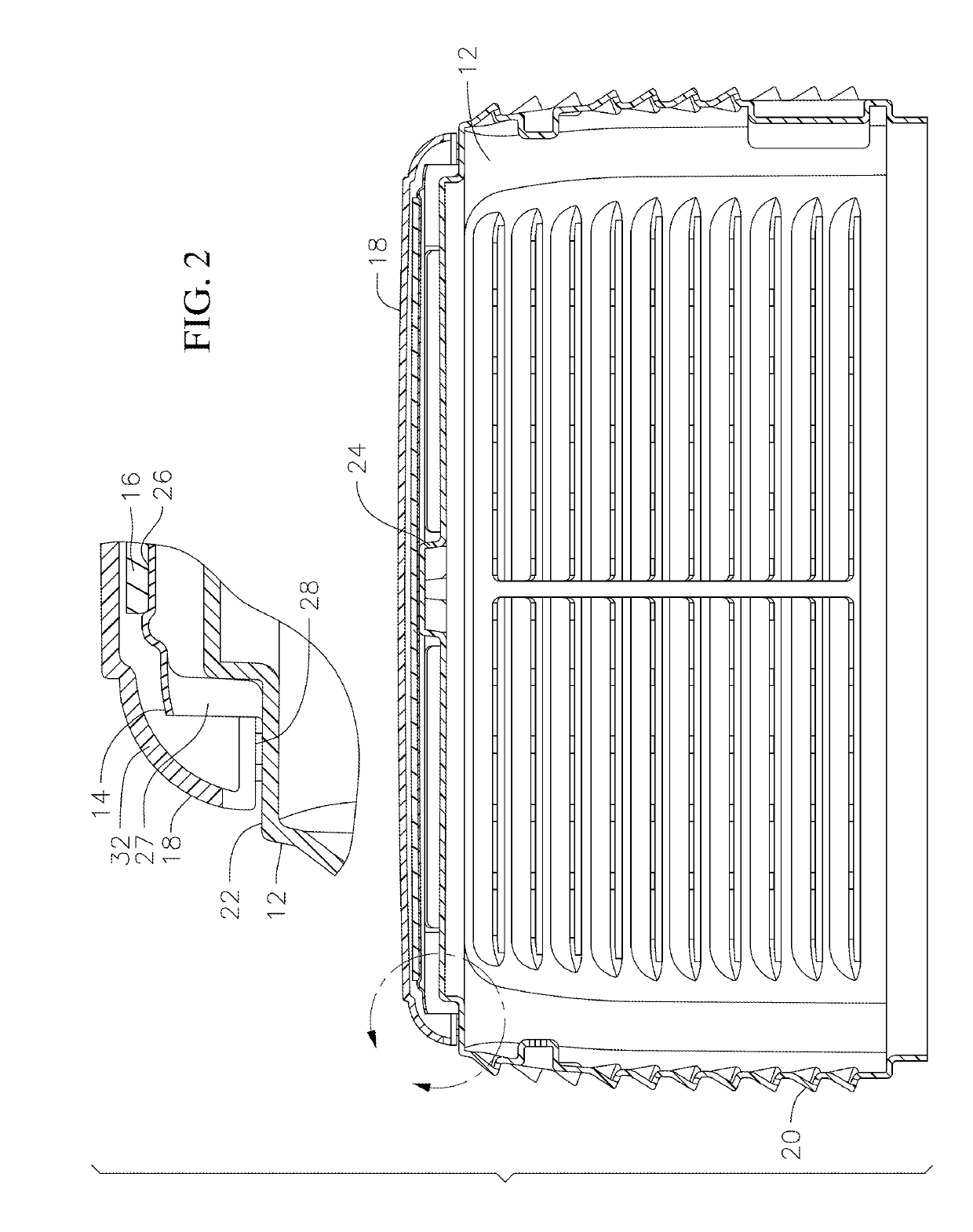
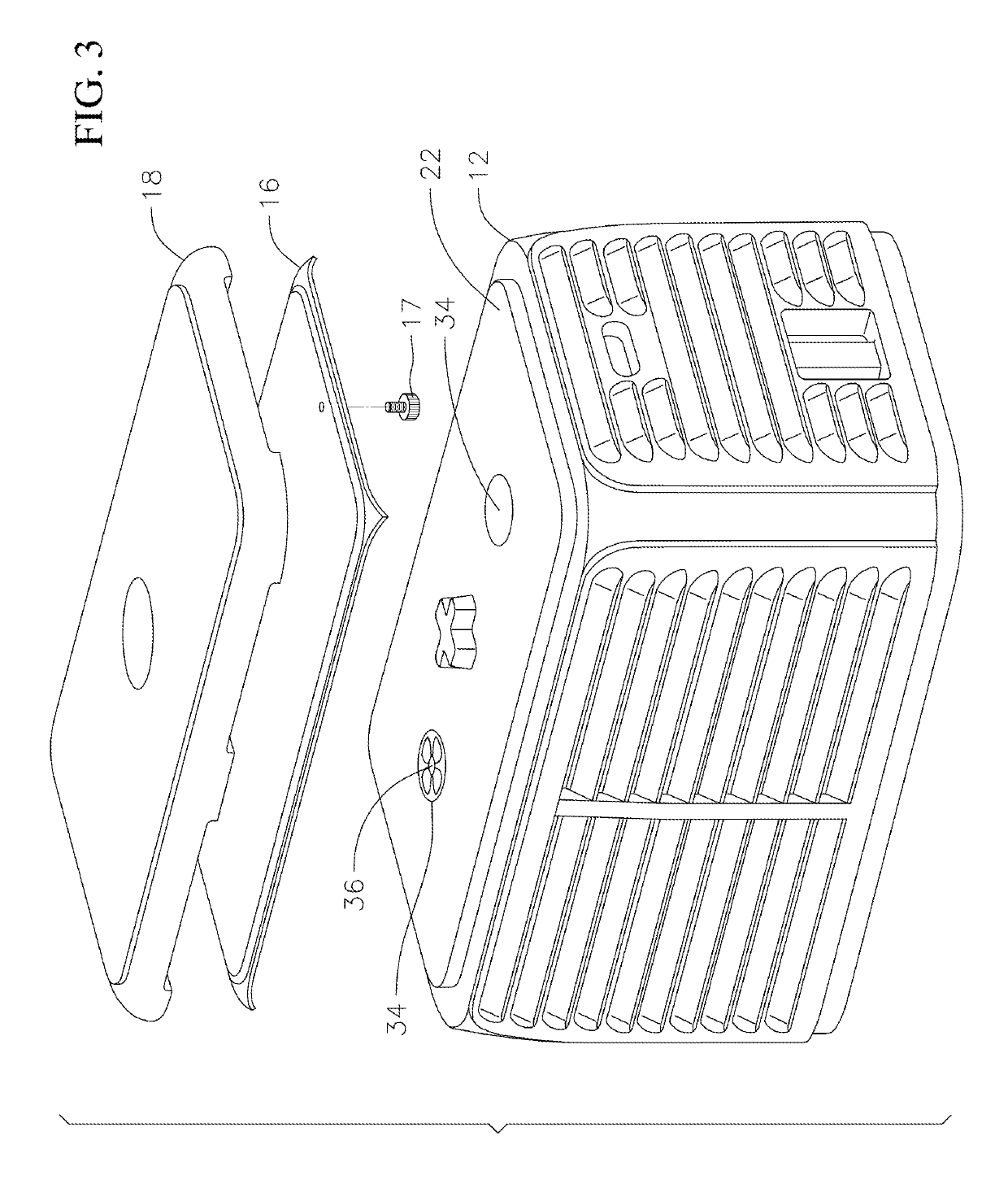
[0013]FIG. 1 is perspective exploded view of a pedestal housing 10 of the present invention. The housing consists of a cover 12, an insulation support 14, an insulation layer 16 and a cap 18. The cover includes a plurality of vents 20 positioned around the sides of the cover and has a top portion 22 upon which is positioned the insulation support 14, insulation 16 and cap 18. As also shown in FIG. 2, the top portion 22 includes a raised portion 24 to provide support for the upper components. The insulation support 14 can sit upon the raised portion 24 and supports the insulation layer 16 under the inside surface of the cap 18. The insulation support 14 includes a barrier layer 26. The barrier layer can be made out of transition metals such as silver, chrome, aluminum, nickel or gold film. Materials other than transition metals that exhibit IR reflective properties can also be used, for example inorganic material such as metal oxides and sulfides w...


PUM


Abstract

A pedestal housing for heat reduction generated by electronic components within the pedestal housing having a cover in which the electronic components are located, a cap positioned on an upper surface of the cover for forming an attic above the cover, a support layer and an insulation layer positioned between the cover and the cap in the attic and a heat and solar barrier layer positioned within the attic for electromagnetic radiation reflection away from the electronic components and electromagnetic radiation absorption from a radiation source and the electronic components.

Description

CROSS-REFERENCE TO RELATED APPLICATION(S)[0001]This application claims priority to and the benefit of U.S. Provisional Application No. 62 / 594,384 filed Dec. 4, 2017 the contents of which are incorporated herein by reference.BACKGROUND[0002]Pedestal housings used in “outside plant” infrastructure for communications and utility companies often house active electronic components which generate heat. The temperature inside the housing increases above ambient conditions due to the heat generated from the active components as well as direct and indirect solar exposure and radiant heat from other objects around the housing. The increase in the internal temperature of the housing transfers heat to the electronic components with adverse consequences. These components tend to fail at shorter and shorter intervals with increases in temperature or operate at reduced rates. As communications companies increase data rates to customers, more active electronics are placed in the outside infrastruct...

Claims


Application Information

Patent Timeline
IPC IPC(8): H05K7/20H05K5/03H05K5/02
CPCH05K7/20427H05K5/03H05K5/0213H05K7/20127H05K7/20418H05K9/0032H05K9/0084H05K9/0086H05K9/0045H05K9/003H05K9/0009
Inventor LEMACKS, MICHAEL A.SAFRANEK, TIMOTHY S.BURKE, EDWARD J.
Owner CHANNELL COMML CORP
Learn More