
Cobalt-doped saturable absorber Q-switches and laser systems

a saturable absorber and cobalt-doped technology, which is applied in the direction of laser details, active medium materials, optical resonator shape and construction, etc., can solve the problems of significantly reducing the efficiency of a q-switch and the power of a laser pulse, and achieves the effect of increasing the efficiency of a saturable absorber q-switch and high aluminum ratio

Inactive Publication Date: 2005-01-04
SAINT GOBAIN CERAMICS & PLASTICS INC
View PDF18 Cites 22 Cited by
  • Summary
  • Abstract
  • Description
  • Claims
  • Application Information

AI Technical Summary

Benefits of technology

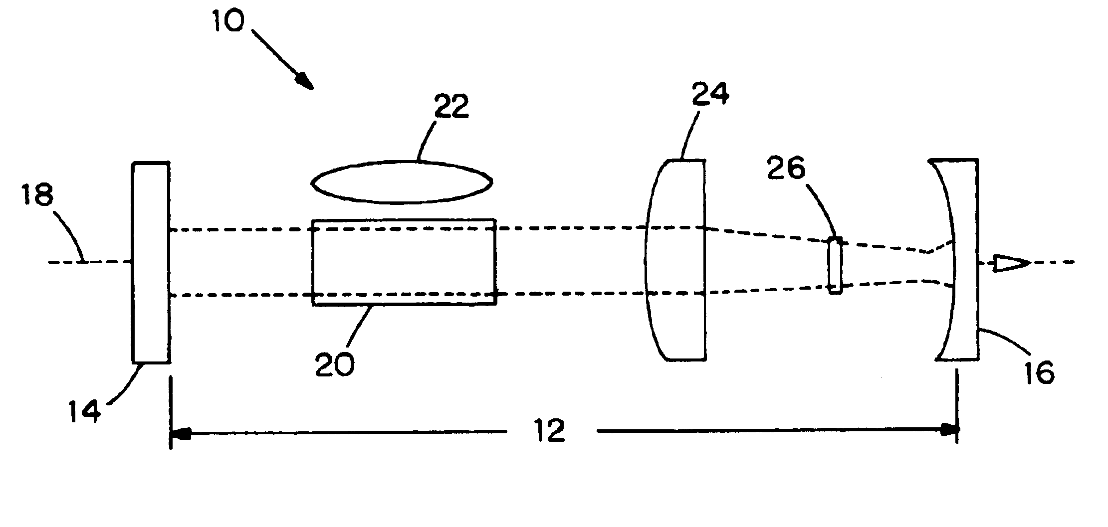
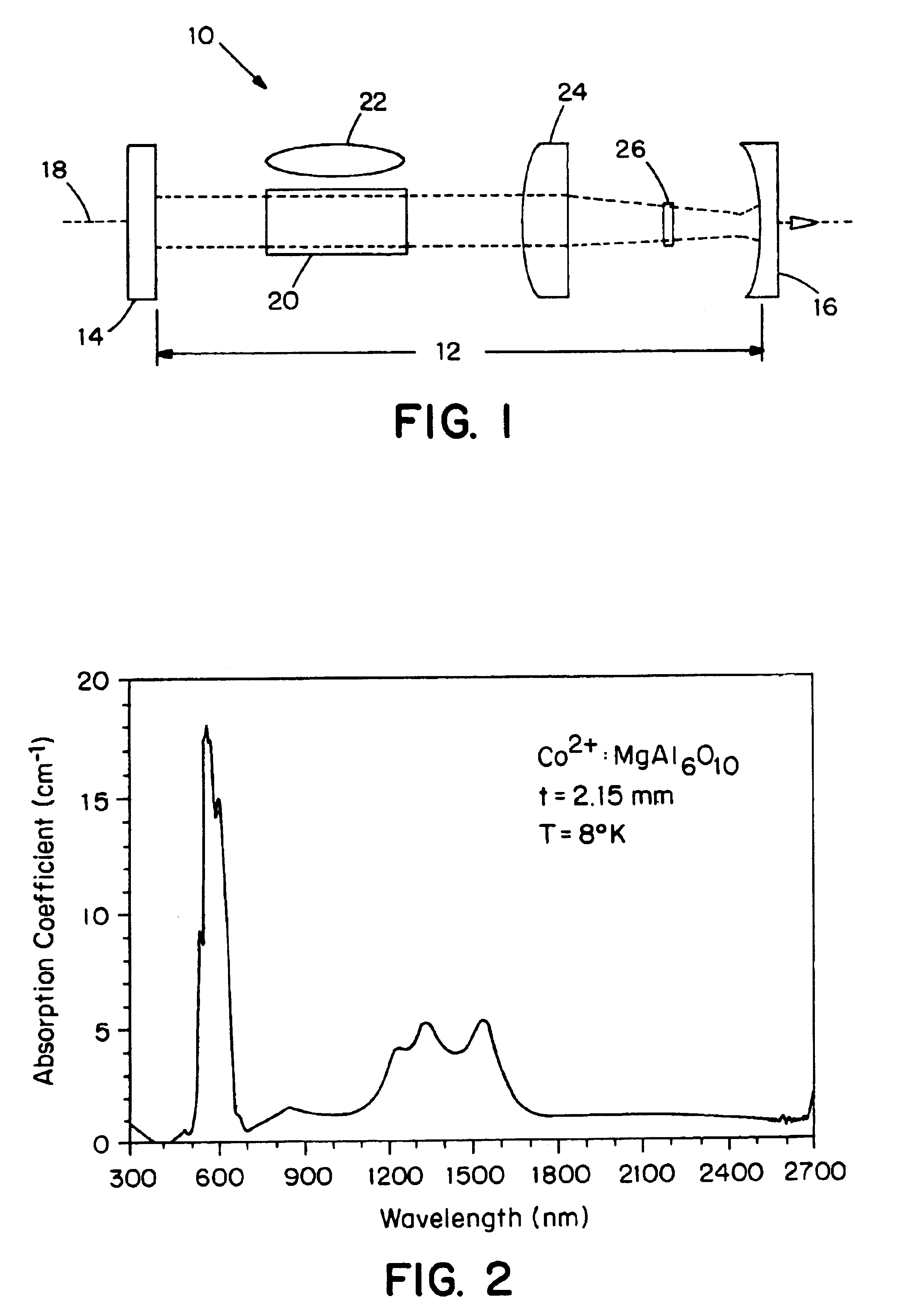
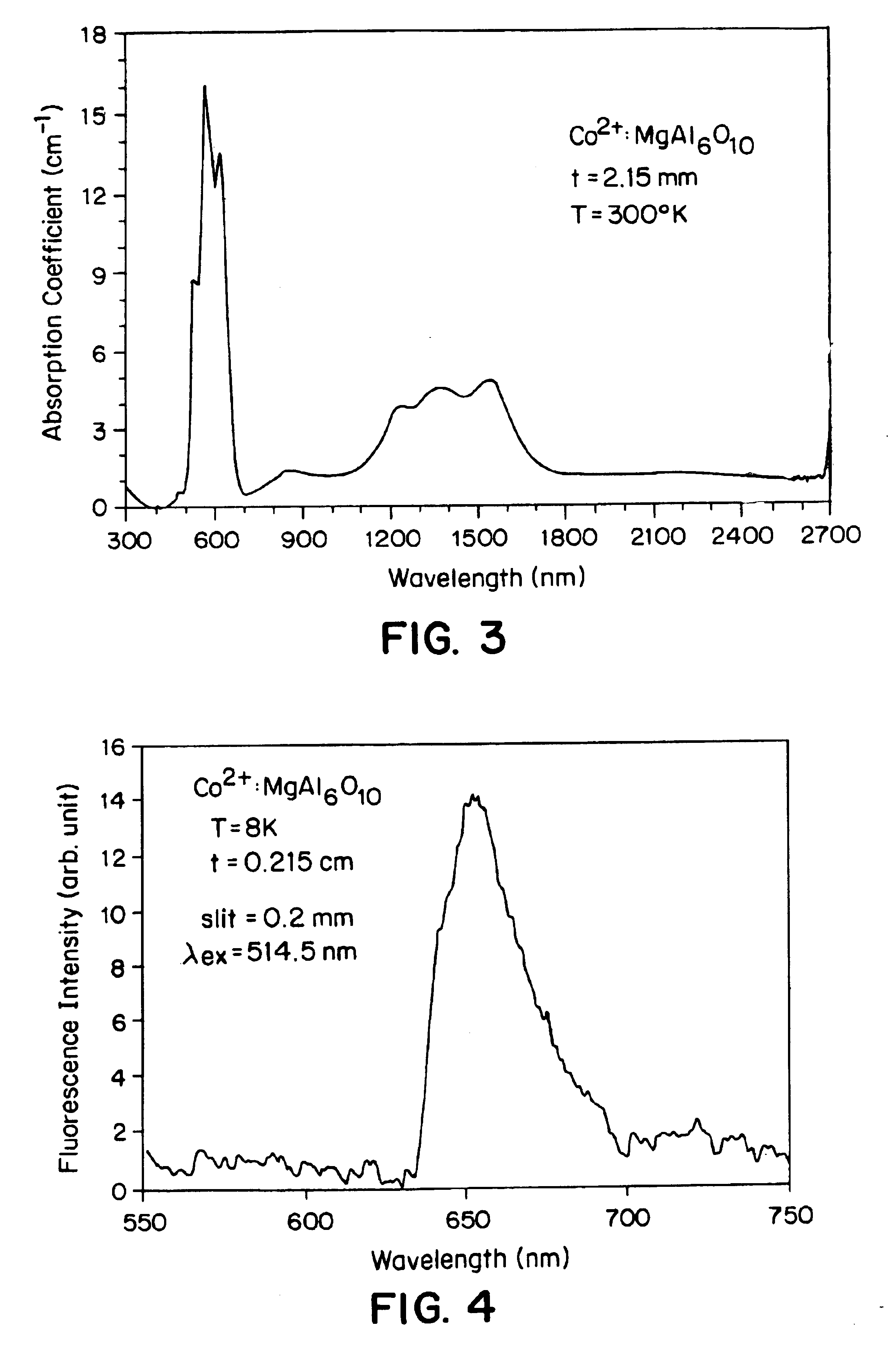
The present invention has several advantages. For example, the saturable absorber Q-switch of the invention includes a ratio of aluminum to magnesium that is greater than that of spinel (MgAl2O4) having an equal amount of cobalt dopant. Despite the relatively high ratio of aluminum to magnesium, most or essentially all magnesium and cobalt dopant occupy only tetrahedral positions of the crystal. Modification of the relative amount of aluminum to magnesium in the saturable absorber Q-switches of the invention enables adjustment of the 4T1 spectrum of cobalt dopant to more closely match a peak of 1544 nanometers, which is the lasing wavelength of erbium:ytterbium:glass (Er:Yb:glass) lasers. In another embodiment, modification of the relative amount of aluminum to magnesium also enables emission of a band at about 1340 nanometers, which is about the lasing wavelength of Nd3+:YAlO3 lasers. Both emission bands can significantly increase the efficiency of saturable absorber Q-switches employed with such lasers. Also, the saturable absorber Q-switches of the invention generally are relatively stable at reduced temperatures, such as at about 8 Kelvin (K).

Problems solved by technology

As a result, the excited states are quickly depopulated, causing energy to be discharged in a single laser pulse.
Further, the efficiency of a Q-switch (and, thus, the power of the laser pulse) is significantly diminished if it does not have an absorption band that matches the lasing transition.
Generally, the efficiency of cobalt-doped spinel Q-switches in Er:Yb:glass and other lasers is limited by the difference in specific absorption bands from the lasing transition wavelengths of such lasers.

Method used


Image

  • Cobalt-doped saturable absorber Q-switches and laser systems
  • Cobalt-doped saturable absorber Q-switches and laser systems
  • Cobalt-doped saturable absorber Q-switches and laser systems

Examples


example 1

General Method for Spinel Growth

The various cobalt doped spinel compositions were grown on 1:1 (MgAl2O4) spinel seed oriented along the <111> axis. Desired compositions were melted in iridium crucibles of sizes appropriate for growth of 30 mm diameter, and 50 mm diameter crystals. The sizes of the melts for larger crystals were circa 3000 gms. The iridium crucibles were inductively heated by 10 kHz RF (radio-frequency) generators. The diameter control was based on controlling the growing crystals weight via controlling the generator output in accordance to the signal from a load cell. On an average, the melting point of the spinel was about 100 degrees higher than the melting point of sapphire. Prior to and during the growth, the melts were maintained under an ambient atmosphere strictly inert. The volatility of the Co oxide dopant was very low. The Co oxide apparently reacted with the spinel components on the heat up, and did not evaporate from the melt. The crystals of 1:1 an...

example 1a

1:3 Spinel Growth

Composition

206.05 gms of MgO0.41 gms of Co3O4 1043.54 gms of Al2O3

The composition was mixed and loaded into 3″ diameter 4-½″ tall iridium crucible of 440 ml volume. The crucible was placed into growth system comprising RF (radio frequency), generator (power) supply, a growth chamber containing the RF coupling coil, zirconium oxide insulation material in an ambient gas enclosure—“Bell Jar,” and an electronic control system. Control was accomplished by controlling the RF generator output in response to the mass of the growing crystal. “ADC” (Automatic Diameter Control) software, supplied by F. Bruni, controlled the shape of growing crystal, temperature increase, and cool down rates, and all other pertinent parameters. The crucible with the oxide mixture was heated to 2150° C. to form a melt. <111> spinel “seed” (small rod-shaped crystal) was immersed (dipped) into the molten mixture. Applying a withdrawal rate of 1 mm / hr along with rotation of the seed at 8 rpm,...

example 1b

1:2 Spinel Growth

Composition

141.56 gms of MgO0.87 gms of Co3O4 1107 gms of Al2O3

The composition was loaded into same crucible as described in Example #1, and placed in an identical growth system. Heat-up time was 6 hours to 2150° C. Rotation rate applied was 8 rpm, pull rate 1 mm / hr under strictly inert atmosphere. Growth time of 150 hours was followed by a 100 hour cool-down period. Grown crystal was harvested at room temperature.

Result: A blue crystalStructure: “Spinel”A0=7.97 A0 Optical Density: 2.4 cm−1


PUM


Abstract

A saturable absorber Q-switch includes a monocrystalline lattice having the formula Mg1-xCoxAlyOz where x is greater than 0 and less than 1, y is greater than 2 and less than about 8, and z is between about 4 and 13. The lattice has tetrahedral and octahedral positions, and most of the magnesium and cobalt occupy tetrahedral positions. In one embodiment, the molar ratio of aluminum to the combined amount of magnesium and cobalt in the monocrystalline lattice can be controlled during growth of the monocrystalline lattice to thereby form a saturable absorber Q-switch that exhibits a 4T1 spectrum for the cobalt ion of at least about 1544 μm. In another embodiment, a laser system, such as an Er:Yr:glass laser system, includes a saturable absorber Q-switch that includes a monocrystalline lattice wherein the molar ratio of aluminum to the combined amounts of magnesium and cobalt exceeds 2:1, and preferably is about 6:1, and wherein essentially all of the magnesium and cobalt components of the monocrystalline occupy tetrahedral positions of the lattice.

Description

BACKGROUND OF THE INVENTIONQ-switching is a method for obtaining single laser pulses of very high power by protracting the period of population inversion of electrons in excited states just prior to emission. Extending the period of population inversions typically can be achieved acousto- or electro-optically by use of shutters, mechanically (with an orthogonal mirror or rotating mirror), or by use of saturable absorbers (in the form of dyes or doped crystals).The term “Q-switching” is a reference to the fact that a “Q-factor” or “Quality factor,” which can be defined as ν / Δνc, where ν is cavity resonance frequency, and Δνc is cavity linewidth, shifts from a very low value to a very high value during laser pulse emission. More specifically, population inversion of electrons is extended by blocking emission from the laser cavity. At the time a laser pulse is to be emitted, the blockage is removed, thereby causing the threshold gain of electrons to be deliberately and suddenly reduced...

Claims


Application Information

Patent Timeline
IPC IPC(8): H01S3/113H01S3/11H01S3/16
CPCH01S3/113H01S3/1608
Inventor KOKTA, MILAN R.PERESSINI, DENNIS L.COOKE, JEFFREY A.GOODNIGHT, KEVIN L.
Owner SAINT GOBAIN CERAMICS & PLASTICS INC
Learn More