
Hard layer-coated tool

a tool and hard coating technology, applied in the field of hard coating tools, can solve the problems of extreme long tool life, and achieve the effects of improving seizure resistance, high feed rate, and high speed

Inactive Publication Date: 2004-09-14
HITACHI TOOL ENG LTD
View PDF11 Cites 19 Cited by
  • Summary
  • Abstract
  • Description
  • Claims
  • Application Information

AI Technical Summary

Benefits of technology

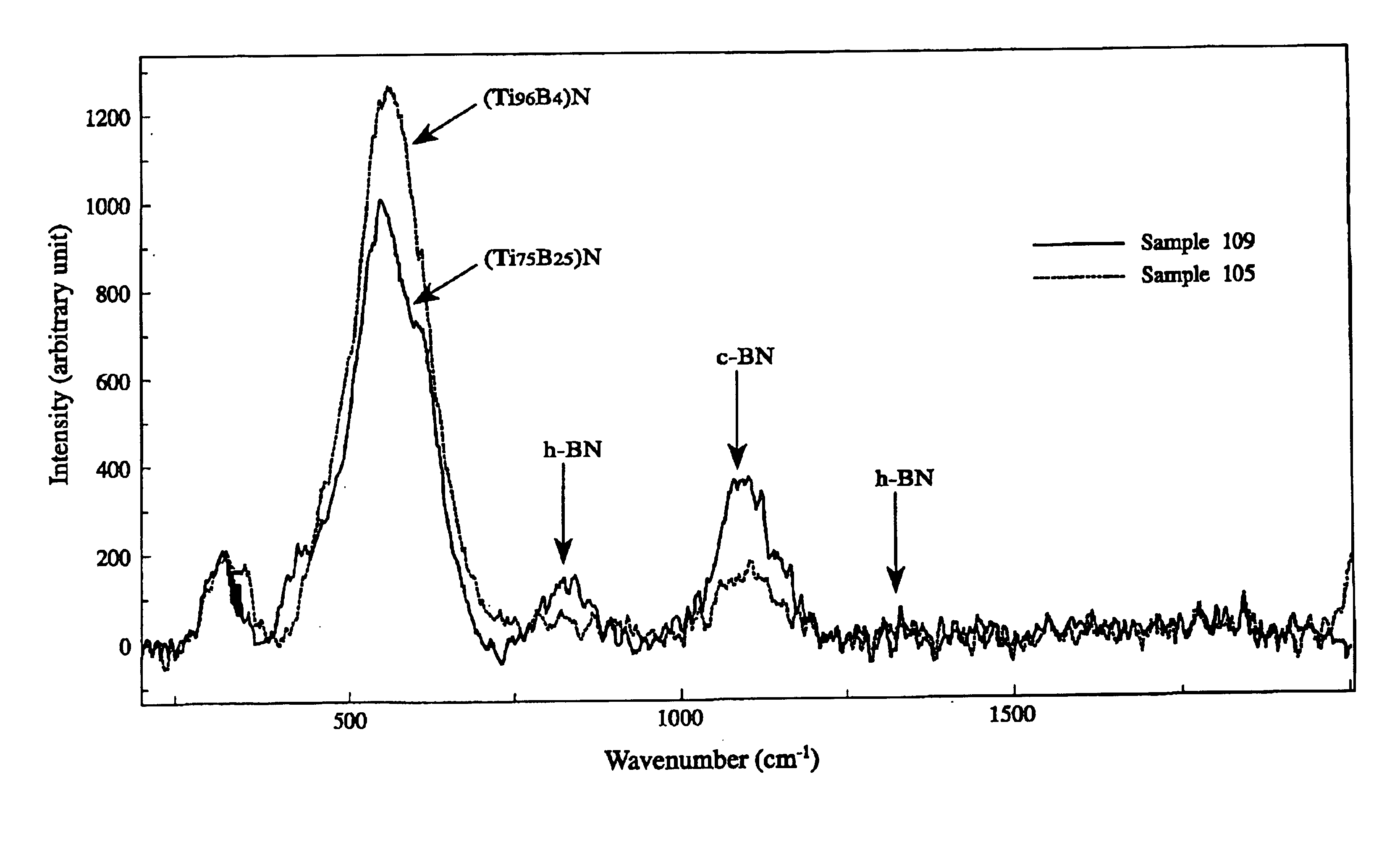
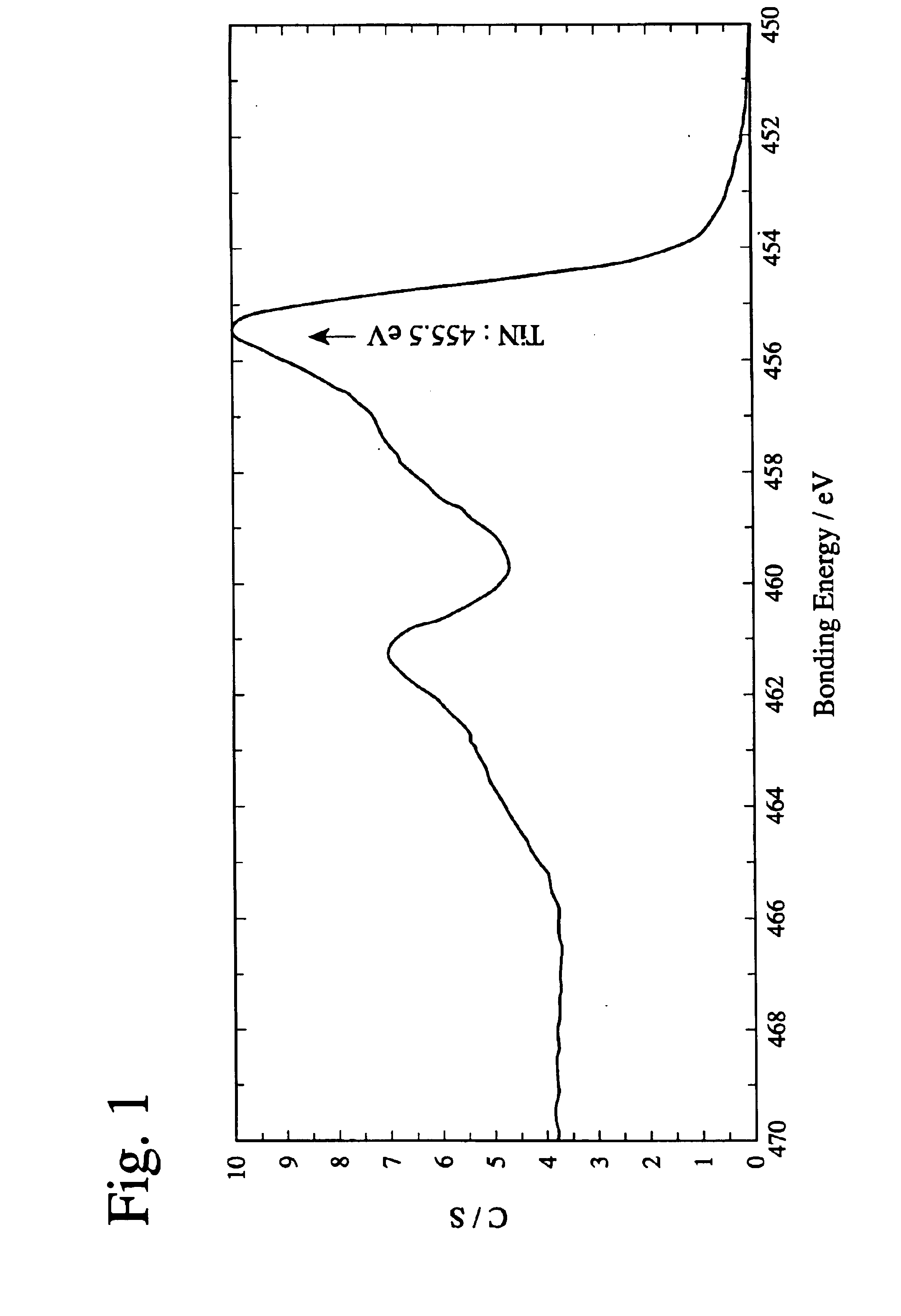
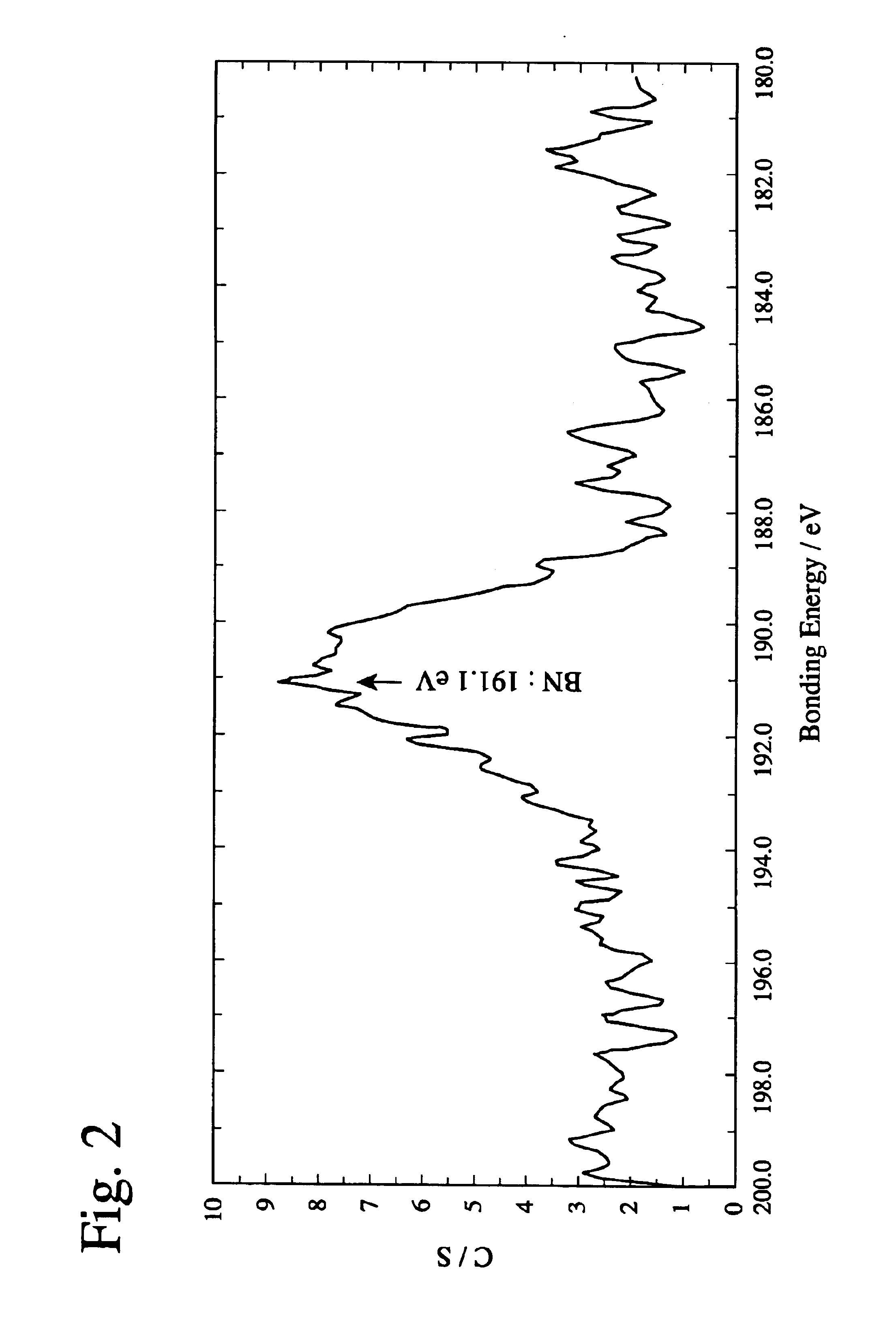
The present invention provides a hard layer-coated tool that has improved seizure resistance and wear resistance, while also maintaining excellent oxidation resistance. The hard coating layer is made of a nitride, carbonitride, oxynitride, or oxycarbonitride layer that contains titanium and boron as metal elements. The hard coating layer is formed by a vacuum film-forming process using a target of a titanium-boron alloy. The hard coating layer contains a boron nitride phase and has a bonding energy of titanium and boron observed in an ESCA analysis. The hard coating layer also has a ratio of c-BN to h-BN of at least 1.0 and a ratio of k / l of at least 1.0. The hard coating layer can be further improved by optimizing coating conditions, such as the addition of BN and the ratio of B to titanium in the hard coating layer. The hard layer-coated tool is suitable for high-speed and high-feed cutting operations and has improved lubricating properties.

Problems solved by technology

The inventors have also found that in a cutting operation in a dry state at a high speed and a high feed, by suppressing a phenomenon of diffusion of elements contained in a work to a hard coating layer, no seizure of a work to a tool occurs and the crater wear resistance of a tool is remarkably improved, resulting in an extremely long tool life.

Method used


Image

  • Hard layer-coated tool
  • Hard layer-coated tool
  • Hard layer-coated tool

Examples


example 2

Using the same targets and conditions as in Example 1, cermet inserts (TNGG 110302R) for turning operation were coated with layers having compositions shown in Table 2. Using the resultant hard layer-coated cermet inserts, works of S53C were cut while turning under the conditions of a cutting speed of 220 m / minute, a cutting depth of 1 mm and a feed of 0.15 mm / rev. with a cutting oil. The cermet composition of each insert was 60TiCN--10WC--10TaC--5Mo.sub.2 C--5Ni--10Co by weight %.

Flank wear tends to increase by heat generation by the crater wear in any hard layer-coated cermet inserts. Thus, the life of the tool was determined at a time when the flank wear reached 0.1 mm. The cutting time until reaching life is shown in Table 2.

example 3

Samples 39-52 of the present invention and Samples 15-19 of Comparative Examples were produced under the same conditions as in Example 1, except that part of Al in Ti--Al alloy targets for the second layers was replaced by other elements shown in Table 3, and evaluated with respect to cutting performance. The results are shown in Table 3.

As is clear from Table 3, the tool life was further improved by adding a third component to a hard TiAl coating layer as the second layer. This is because the solid solution strengthening of a (TiAl)N layer occurred by the addition of a third component, resulting in improvement in oxidation resistance.

example 4

Using an arc-ion plating apparatus, and selecting those desired from targets of various alloys as metal element sources, and a nitrogen gas, an oxygen gas and a methane gas as reaction gases depending on the targeted compositions of hard coating layers, milling inserts (bottom-tool inserts of RDMW 1604MOTN) made of cemented carbide (P40 grade) for cutting tools according to JIS B 4053 were provided with various hard coating layers shown in Table 5 under the conditions shown in Table 4. Incidentally, other conditions than shown in Table 4 are the same as in Example 1. The thickness shown in Table 5 was the thickness of each hard coating layer on a face, and the first layers and the second layers were alternately laminated in the case of multi-layer structures of three layers or more. Other coating conditions than described above are the same as in Example 1.

Using the resultant hard layer-coated inserts, each work of SKD61 (hardness HRC 45) was face-milled in a width of 100 mm and a l...


PUM

PropertyMeasurementUnit
total thicknessaaaaaaaaaa
bias voltageaaaaaaaaaa
temperatureaaaaaaaaaa

Abstract

A tool coated with a hard Ti / B layer having fine boron nitride particles dispersed therein, wherein the bonding energy of B and N is observed in an ESCA analysis of the hard coating layer; wherein peaks of c-BN and h-BN is detected in an Raman spectroscopy of the hard coating layer; wherein a ratio Q1 / Q2 of a peak intensity Q1 of c-BN to a peak intensity Q2 of h-BN is 1.0 or more; wherein a half-value width Z of a (200) face in an X-ray diffraction of the hard coating layer is in a range of 0.3° to 0.6°; and wherein a ratio K / L of a face thickness K to a flank thickness L in the tool is 1.0 or more, whereby the hard coating layer has high hardness, high lubricating properties and excellent crater wear resistance, with chemical reactions with a work suppressed.

Description

The present invention relates to a hard layer-coated tool used for cutting metal materials, etc., particularly to a hard layer-coated tool having excellent crater wear resistance for use in high-speed cutting and dry cutting.Cutting tools coated with TiN, Ti (CN), (TiAl)N, etc. are conventionally used widely. However, layers of TiN or Ti (CN) fail to exhibit sufficient oxidation resistance and wear resistance during high-speed cutting. Because a (TiAl)N layer has superior oxidation resistance to that of TiN and Ti (CN), it is used under cutting conditions that a tool edge tip is subjected to high temperatures. However, seizure occurs at a tool edge tip during cutting at high temperatures, failing to achieve sufficient tool life.JP 2001-293601 A discloses a wear-resistant TiN layer containing fine compound particles of BN, TiB.sub.2, TiB, etc. It is described in this reference that these fine compound particles are amorphous and have function to improve the hardness of the layer. Tho...

Claims


Application Information

Patent Timeline
Patent Type & Authority Patents(United States)
IPC IPC(8): C23C14/06C23C30/00
CPCC23C14/0688C23C28/044C23C28/048C23C28/42C23C30/005Y10T428/265
Inventor KUBOTA, KAZUYUKISHIMA, NOBUHIKO
Owner HITACHI TOOL ENG LTD
Learn More