Eureka AIR delivers breakthrough ideas for toughest innovation challenges, trusted by R&D personnel around the world.

Color filters for liquid crystal display panels and method of producing the same

a technology of liquid crystal display and color filter, which is applied in the field of color filter for liquid crystal display (lcd) panels, can solve the problems of increasing production costs, difficulty in controlling the position of colors and uniform thickness of various colors, and limited color pattern patterns, so as to reduce the partitions needed for lithography and stop further oxidation

Inactive Publication Date: 2004-03-09
IND TECH RES INST
View PDF4 Cites 84 Cited by
  • Summary
  • Abstract
  • Description
  • Claims
  • Application Information

AI Technical Summary

Benefits of technology

is to provide a color filter for LCD panels, in which the multicolor layer of the color filter is formed directly from the oxidization of a metal layer on the substrate, without high molecular material, such as dispersion agent, adhesion agent, and color-absorbing layer. As a result, deficiency in resistance to chemicals, heat and light is avoided.
Though the oxidation is done by strong acid in the embodiments, high temperature or laser are also applicable to provide necessary energy. In particular, laser exhibits the ability to reduce the partitions needed for lithography.

Problems solved by technology

(1) Printing method: Three primary colors are sequentially printed onto a substrate using a screen board. However it is difficult to control the positions of colors and the uniformity of the thickness of various colors.
(2) Electro-deposition method: Ground colorants are sequentially electro-deposited to predetermined positions by electrical-ionic dispersing agent. But, patterns of colors are limited due to the thickness of colorant affected by difficulty in controlling the uniformity of current.
(3) Colorant dispersion method: Non-ionic surfactant is used as dispersion agent for high molecular colorant to make a colored photosensitive agent. A substrate coated with the photosensitive agent is then subjected to photolithography to obtain expected colored areas. However, three courses of lithography are required, thereby increasing production costs.
(4) Dyeing method: A substrate coated with a dyeable photosensitive agent is exposed to obtain partitioned areas, followed by localized coloring to obtain expected color areas. However, this method exhibits reliability problems, such as deficiency of chemical resistance, heat resistance and litho-resistance.
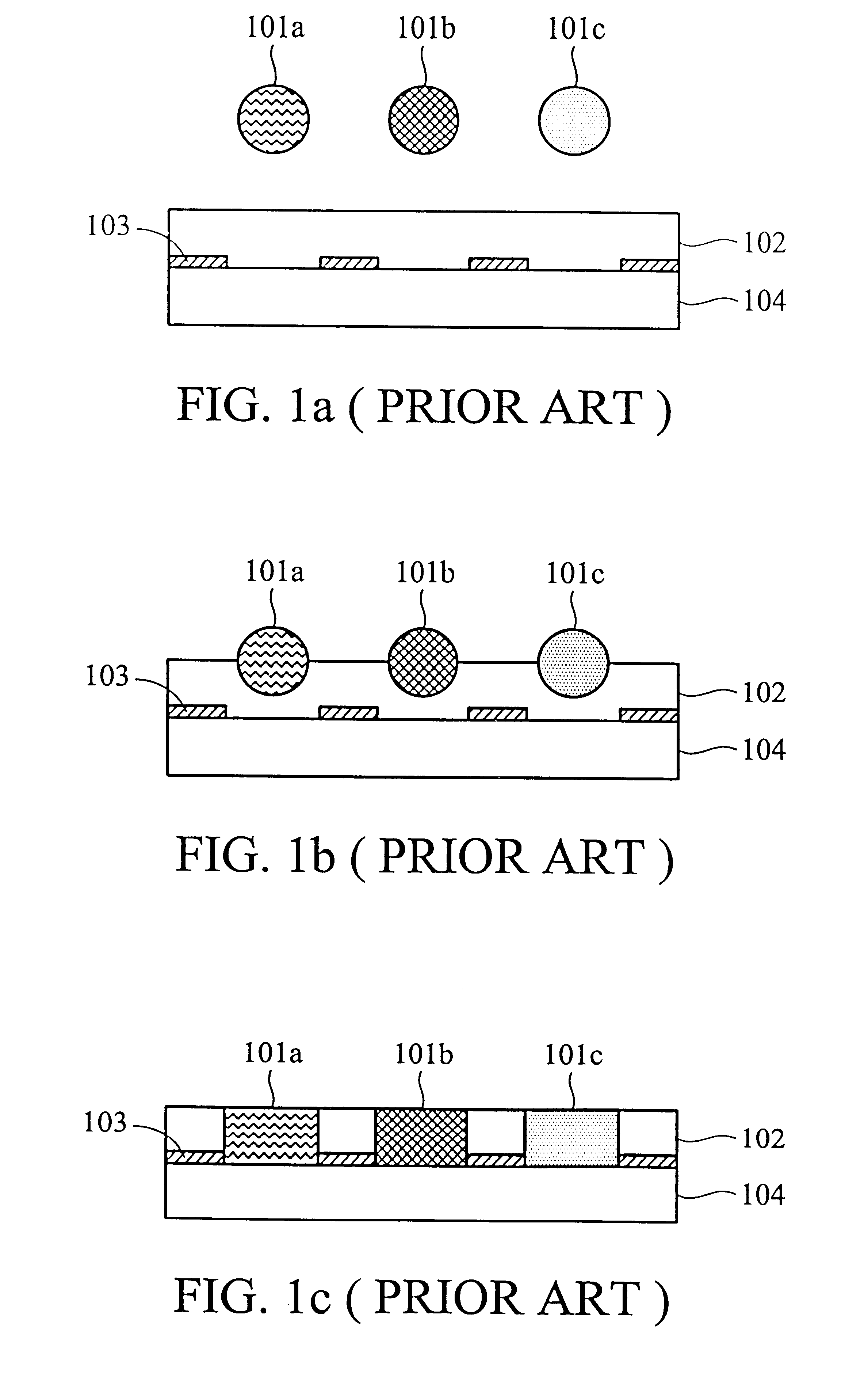
(5) Ink-jet method: Shown in FIGS. 1a-1c, where 104 represents a substrate, 103 represents black matrix, 102 represents an ink-absorbing layer, and 101a-101c represent ink in different colors. In FIG. 1a, a substrate 104 is prepared for ink-jetting; and contact of ink with the substrate is shown in FIG. 1b. FIG. 1c illustrates the completion of colored substrate. In this method, a substrate is firstly coated with an ink-absorbing layer, followed by another smooth coating of photoresist agent in thick-film. Next, the substrate is subjected to photolithography to attain partitioned areas, followed by ink-jetting to obtain expected colored areas. In this method, three primary colors (red, green, blue) are printed onto the substrate simultaneously, thus the process time and costs for material are more economical than the colorant dyeing method. However, high molecular material is required as adhesion promoter or dispersion agent, which is mostly deficient in resistance to chemicals, heat and light.
Hence, gaps easily occur between different colors.
Also, the thickness of colors is difficult to control.
Consequently, there are problems in product quality.

Method used


Image

  • Color filters for liquid crystal display panels and method of producing the same
  • Color filters for liquid crystal display panels and method of producing the same
  • Color filters for liquid crystal display panels and method of producing the same

Examples


embodiment

1.sup.st Embodiment

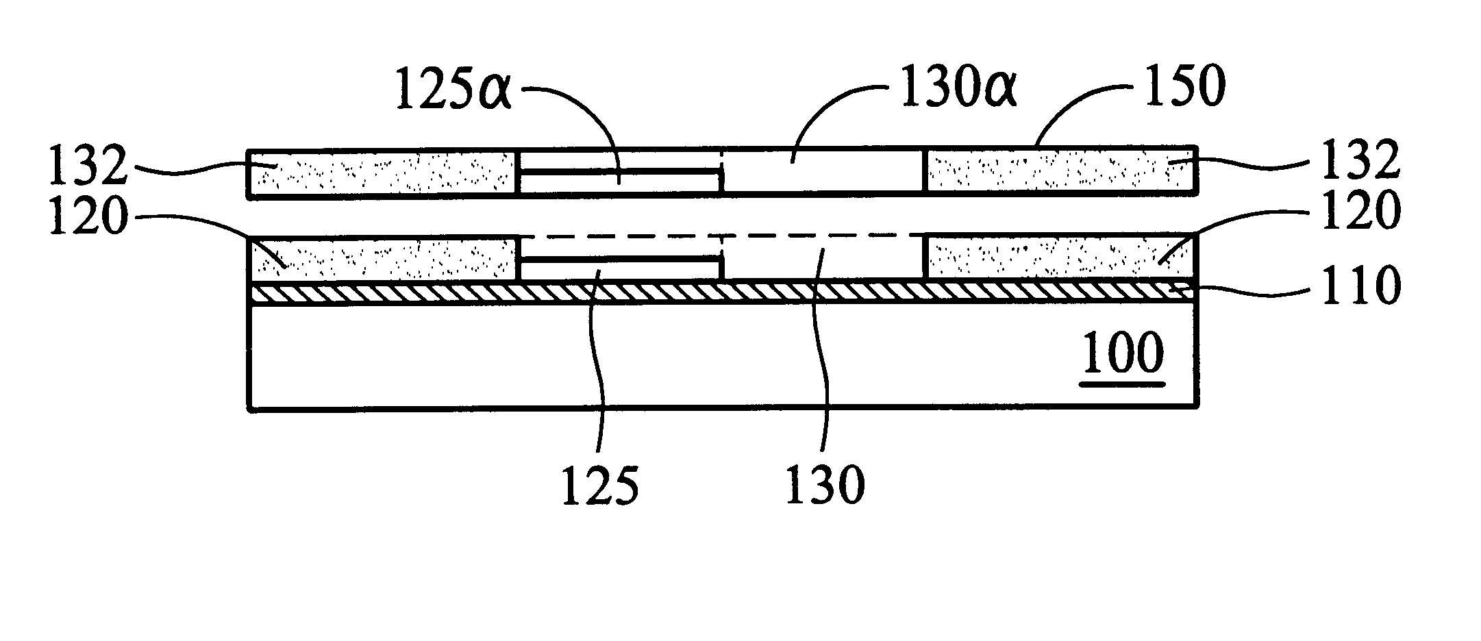
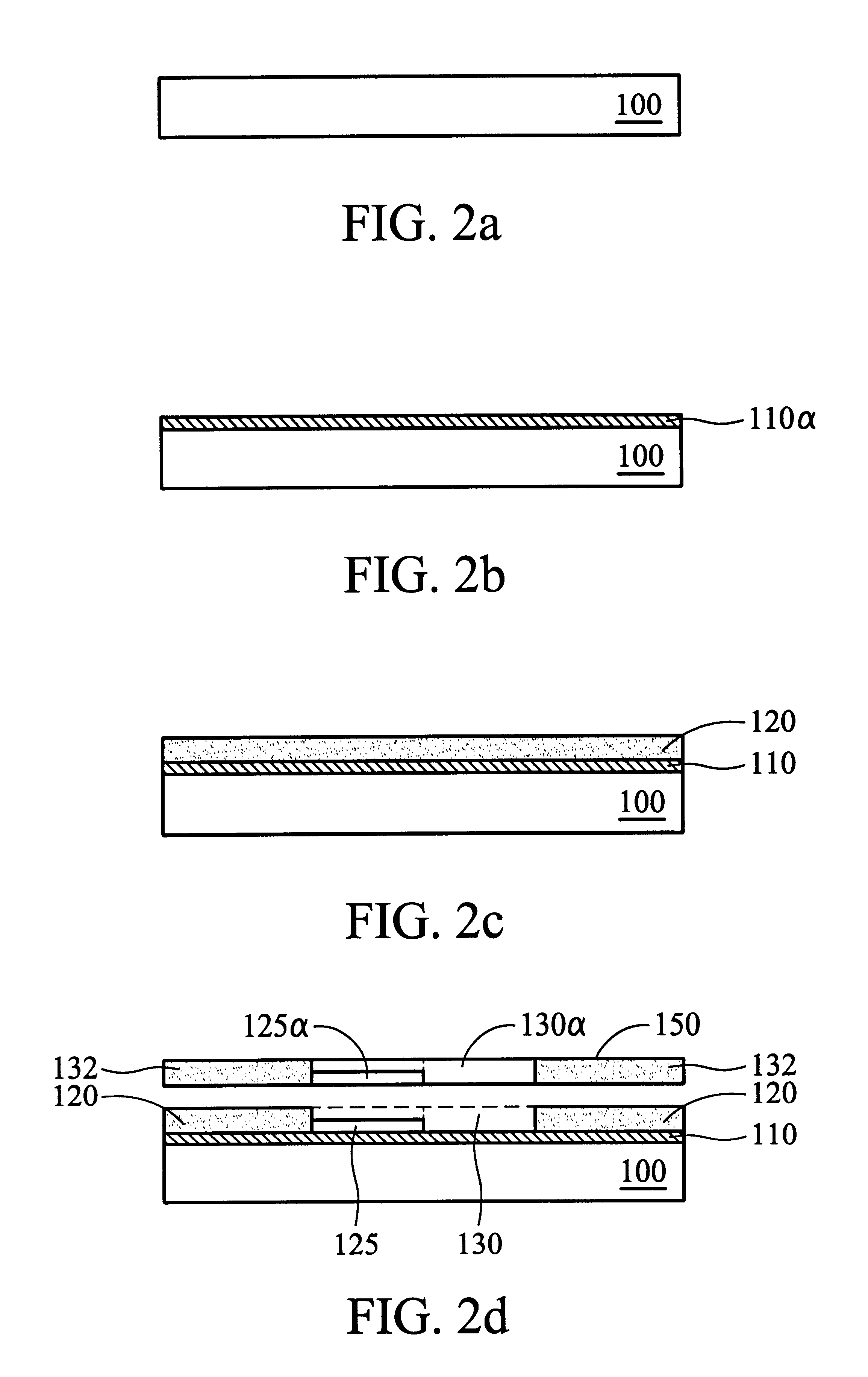
FIGS. 2a-2f illustrate the process according to the 1.sup.st Embodiment of the invention to produce a color filter without black matrix. First, in FIG. 2a, a transparent substrate 100 is provided, followed by forming a Cr layer 110.alpha. by physical vapor deposition (PVD) on the substrate 100, as shown in FIG. 2b. Next, the Cr layer is completely oxidized to form a first color layer 110 (blue).

The formation of metal layer by PVD can be replaced with chemical vapor deposition (CVD) as well. The thickness of the Cr layer is at least a layer of Cr atom or Cr-containing alloy, within the range of 60-5000 .ANG.. The transparent substrate is glass or polymer. As for the Cr layer, other metals such as Cu, Al, Fe and Ni are applicable as well. The oxidation step is performed by a strong acid, such as chromic acid, sulfuric acid, nitric acid or combinations thereof. A combination of chromic acid and sulfuric acid is used in this embodiment.

Then, in FIG. 2c, a positive pho...


PUM

PropertyMeasurementUnit
thicknessaaaaaaaaaa
transparentaaaaaaaaaa
areaaaaaaaaaaa

Abstract

A color filter for liquid crystal display panels. The filter includes a transparent substrate with a metal layer formed thereon, and a first color layer, a second colour layer and a third color layer are integrally formed with the same metal layer. The invention also provides a method for producing the color filter described above. The method applies the theory of oxidizing metal layers by repeatedly exposing and oxidizing to form a color filter having multiple integrally formed colors. Depending on requirements, the color filter of the invention also includes the black matrix that is often included in liquid crystal display panels.

Description

1. Field of the InventionThe present invention relates to a color filter for liquid crystal display (LCD) panels, in particular, a color filter with integrally formed multicolor layer and a method of producing the same.2. Description of the Prior ArtIn general, conventional methods for producing color filters for LCD panels utilize various mechanisms to coat three primary colors (red, green and blue) onto predetermined positions of a substrate, followed by separation, filtration and the addition of adhesive. Examples of such methods includes printing, electro-deposition method, colorant dispersion, dyeing, ink-jet etc. The above-mentioned methods and their disadvantages are further discussed as follows:(1) Printing method: Three primary colors are sequentially printed onto a substrate using a screen board. However it is difficult to control the positions of colors and the uniformity of the thickness of various colors.(2) Electro-deposition method: Ground colorants are sequentially e...

Claims


Application Information

Patent Timeline
Patent Type & Authority Patents(United States)
IPC IPC(8): G02F1/13G02F1/1335G02B5/20G02B5/00
CPCG02B5/201G02F1/133514G02F1/133516
Inventor LU, CHUN FUSHIEH, FANNYCHEN, CHIN-TAI
Owner IND TECH RES INST
Why Eureka
Eureka Blog
Learn More