Eureka AIR delivers breakthrough ideas for toughest innovation challenges, trusted by R&D personnel around the world.

Membrane-separated, bipolar multicell electrochemical reactor

a multi-cell, membrane-separated technology, applied in the field of electrochemical reactors, can solve the problems of severe corrosion phenomena of conductive parts, complicated and time-consuming operations, and aggravated problems

Inactive Publication Date: 2003-04-29
SQUIRREL HLDG
View PDF6 Cites 117 Cited by
  • Summary
  • Abstract
  • Description
  • Claims
  • Application Information

AI Technical Summary

Benefits of technology

In this way, by-pass current may only be "driven" by a voltage difference of about one-cell voltage and becomes practically negligible and above all it does not cause any corrosion on conductive parts.
Besides outstandingly reducing the pressure drop suffered by the electrolyte flowing through the respective flow chambers in series from one end to the opposite end of the battery, this arrangement of interleaved "source" and "drain" channels, suitably cut through the thickness of the three-dimensional porous electrode, is found to outstandingly enhance the electrochemical performance of the battery because of a far more evenly distributed current density over the entire cell area of the battery.

Problems solved by technology

The assembling of a large number of bipolar elements in electrical series as required in redox batteries to reach an adequate voltage at the two ends of the battery, the positioning of innumerable gaskets for sealing the outer perimeter of each electrolyte flow chamber and the perimeter of the distinct through holes of the frames for defining the inlet and outlet manifolds for the two electrolytes and the final tightening of the filter press assembly by tie rods compressing the two end elements over the stack, are extremely delicate and time consuming operations that require particularly skilled technicians.
The parallel flow of the two electrolytes through the respective flow chambers poses serious problems in terms of minimization of so-called stray or by-pass electric currents in uninterrupted liquid veins of electrolyte, due to the fact that the electrolyte present in the manifolds offer innumerable paths for these by-pass or stray currents, driven by mutual voltage differences existing among the various bipolar elements functioning in electrical series between the two end electrodes on which the full battery voltage difference insists.
By-pass or stray currents decrement the energy efficiency of the conversion system, but more seriously they cause severe corrosion phenomena on conductive parts (e.g.: carbon) because of extremely high half-cell voltages at the conductor surface.
This problem is aggravated when passing from a parallel flow of the electrolyte through all the respective flow chambers from a common inlet manifold to common outlet manifold to a cascade flow from one chamber to the next and so forth from one end to the opposite end of the stack.

Method used


Image

  • Membrane-separated, bipolar multicell electrochemical reactor
  • Membrane-separated, bipolar multicell electrochemical reactor
  • Membrane-separated, bipolar multicell electrochemical reactor

Examples


Embodiment Construction

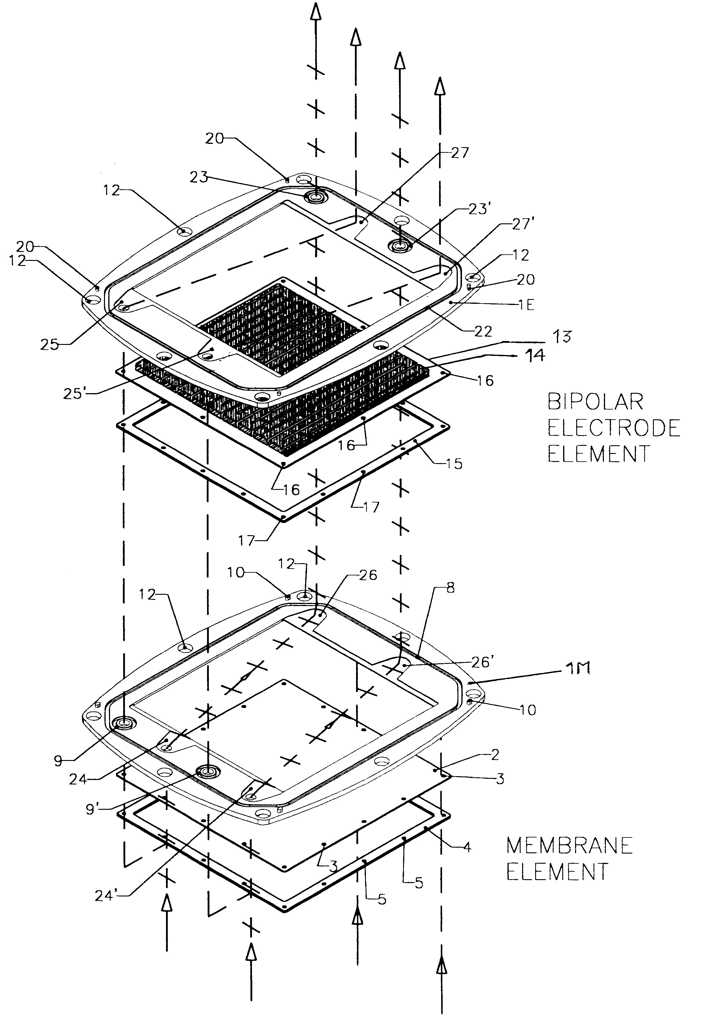
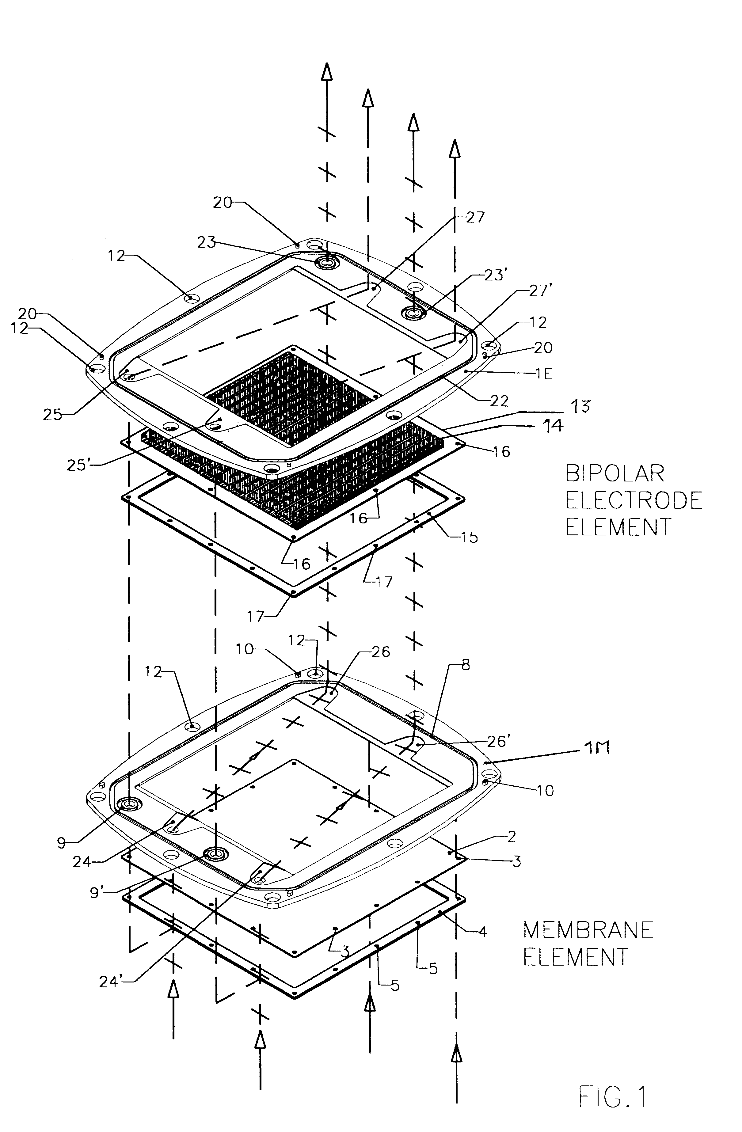
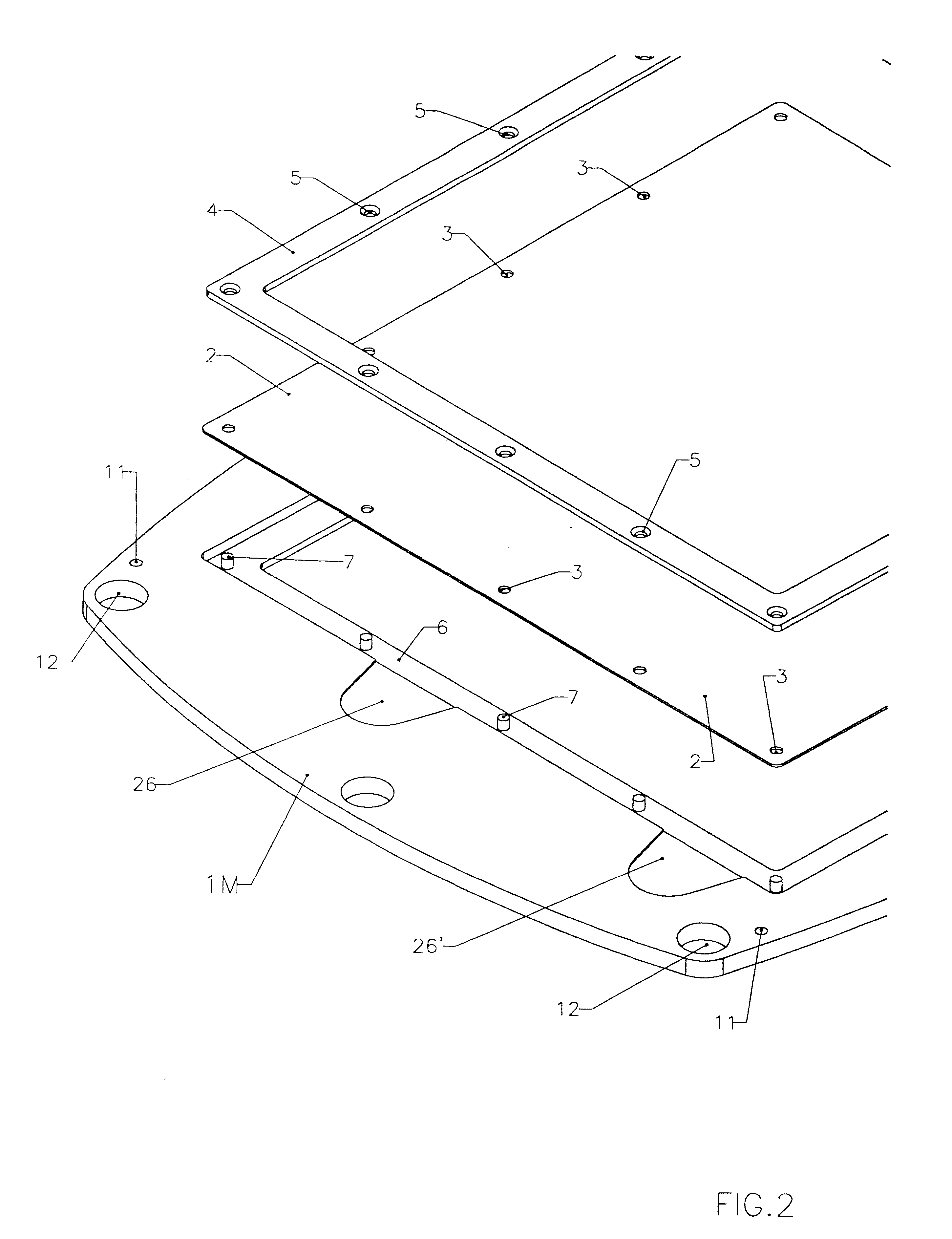
FIGS. 1, 2, 3, 4 and 5 illustrate a battery realized according to a preferred embodiment of the present invention.

The exploded view of FIG. 1, representing the two types of the pre-assembled elements, namely a membrane element and a bipolar electrode plate element, provides an explicative overview of the architecture of the invention, according to a preferred embodiment.

The frame portion 1M of membrane element and the frame portion 1E of a bipolar electrode element are under many aspects substantially similar. Both may be of a molded plastic material such as for example polypropylene, different molds being employed for the two types of frames 1E and 1M, for implementing suitably different keying pins and sockets.

According to a most preferred embodiment, the molded plastic frames 1M and 1E define a rectangular inner window, however, the outer perimeter of the frame is not rectangular but has a peculiarly curved shape, determined by the fact that each side of the frame has a convex ou...


PUM

PropertyMeasurementUnit
pressureaaaaaaaaaa
currentaaaaaaaaaa
electrically nonconductiveaaaaaaaaaa

Abstract

A multicell assembly is constituted by alternately stacking two types of pre-assembled elements: a bipolar electrode holding subassembly and a membrane holding subassembly. The alternate stack of elements is piled over a bottom end element and the stack is terminated by placing over the last membrane holding element a top end electrode element. Each bipolar plate electrode holding element and each ion exchange membrane separator holding element includes a substantially similar rectangular frame piece, made of an electrically nonconductive and chemically resistant material, typically of molded plastic material, having on its upper (assembly) face grooves for receiving O-ring type gasket means, and having through holes and recesses in coordinated locations disposed along two opposite sides of the rectangular frame forming, upon completion of the assembling, ducts for the separate circulation of the negative electrolyte and of the positive electrolyte through all the negative electrolyte flow chambers and all positive electrolyte flow chambers, respectively, in cascade.

Description

1. Field of the InventionThis invention relates to electrochemical reactors for conducting reduction and oxidation reactions in respective positive and negative liquid electrolytes, without gas evolution at the electrodes. More specifically the invention relates to a membrane-separated, bipolar multicell electrochemical reactor for implementing a redox flow battery system.2. Description of Related ArtRedox flow battery systems are increasingly attracting interest as efficient energy conversion systems. Among redox couple candidates, the all vanadium redox system being one of the most preferred.Structurally, the electrochemical reactors that have been proposed for redox flow battery systems, have been derived from the electrochemical reactor structures developed for general electrolysis processes, the only adaptation having concerned the materials employed as electrodes.Generally, the electrochemical reactors used as redox batteries are conventionally composed of a stack of bipolar p...

Claims


Application Information

Patent Timeline
Patent Type & Authority Patents(United States)
IPC IPC(8): H01M8/02H01M8/24H01M8/18
CPCH01M8/0273H01M8/246Y02E60/50H01M8/2483H01M8/0263H01M8/24H01M8/02H01M8/242
Inventor BROMAN, BARRY MICHAELZOCCHI, ANDREA
Owner SQUIRREL HLDG
Why Eureka
Eureka Blog
Learn More