Opto-mechanical device

a technology of optical mechanical devices and scalar effects, applied in the direction of positive displacement liquid engines, optical radiation measurement, instruments, etc., can solve the problems that the application of the opto-mechanical device using this scalar effect is limited, and achieve the effects of reducing the size of the devi

Inactive Publication Date: 2002-05-21
CAMBRIDGE UNIV TECH SERVICES LTD
View PDF1 Cites 20 Cited by
  • Summary
  • Abstract
  • Description
  • Claims
  • Application Information

AI Technical Summary

Benefits of technology

The mechanical strain in the actuating member resulting from its illumination is provided by two different effects. Firstly there is a scalar effect in which when an initially isotropic semiconducting glassy matrix is illuminated by unpolarised light it expands. This expansion produces a metastable state and the semiconducting glassy matrix can be returned to its isotropic state by heating. An opto-mechanical device using this scalar effect has only limited application.
The secondary system may be any one which responds to mechanical strain or movement and thus, for example, the secondary system may include an optical lever comprising a laser beam which is reflected from the actuating member or an element connected to it and then impinges upon a position-sensitive photo-detector so that as the actuating member moves or bends the effect of its movement turns the optical lever formed by the laser beam so that it moves along the position-sensitive photo-detector. The output of the position-sensitive photo-detector then gives an indication of the mechanical movement of the actuating member and hence of the illumination applied to it. The actuating member may include a metal electrode and in this case the mechanical movement of the actuating member and its associated electrode towards or away from an associated electrode provides a change in capacitance between the two electrodes. This change in capacitance may be monitored to give a representation of the mechanical movement of the actuating member and hence of the illumination applied to it. Equally, the substrate may be formed by a piezo-resistive material the resistance of which changes as a result of a strain imposed upon it. Accordingly, in this case, as a result of a change in strain in the substrate caused by the strain in the semiconducting glassy matrix, the electrical resistance varies so resulting in a change in resistance being used to provide an indication of the change in strain of the semiconducting glassy matrix and hence its illumination. A further way in which the actuating member can be used to control a secondary system is in the case where the secondary system is a fluidic system. In this case the actuating member may be arranged close to a nozzle in a fluidic system so that as the illumination of the actuating member varies and hence its displacement varies, it gets closer to or further away from the nozzle so varying the rate of flow through the nozzle and hence the back pressure upstream of the nozzle. In this way the opto-mechanical device can be used to influence a fluidic system and thus produce a light sensor or a controller which is responsive to the light input into the device which, being completely free from electrical contacts, would be intrinsically safe in an explosive environment.
When the elements forming the semiconducting glassy matrix are in non-stoichiometric proportions the exact composition of it can be tailored to influence and suit its intended use. Firstly, by selecting and varying the proportions of the element or other elements in the semiconducting glassy matrix the band gap of the semiconductor can be varied and so matched to the energy of the light which is used to illuminate the actuating member. Clearly this can be used to make the actuating member selective to light of a predetermined wavelength where the actuating member is used to detect light of a predetermined wavelength or alternatively merely to match the actuating member to the wavelength of light output by a light source used with the opto-mechanical device and thereby optimise its sensitivity. It is also possible to change the rigidity of the glass material and, in this way affect the amount of expansion and contraction that occurs. For example, introducing iodine into the semiconducting glassy matrix appears to make it less rigid and so causes greater expansion and contraction of the matrix for a given change in illumination. Equally, the introduction of germanium into the semiconducting glassy matrix appears to make it more rigid and so results in a lower expansion and contraction for the given change in illumination.

Problems solved by technology

Firstly there is a scalar effect in which when an initially isotropic semiconducting glassy matrix is illuminated by unpolarised light it expands.
An opto-mechanical device using this scalar effect has only limited application.

Method used


Image

  • Opto-mechanical device
  • Opto-mechanical device
  • Opto-mechanical device

Examples


Embodiment Construction

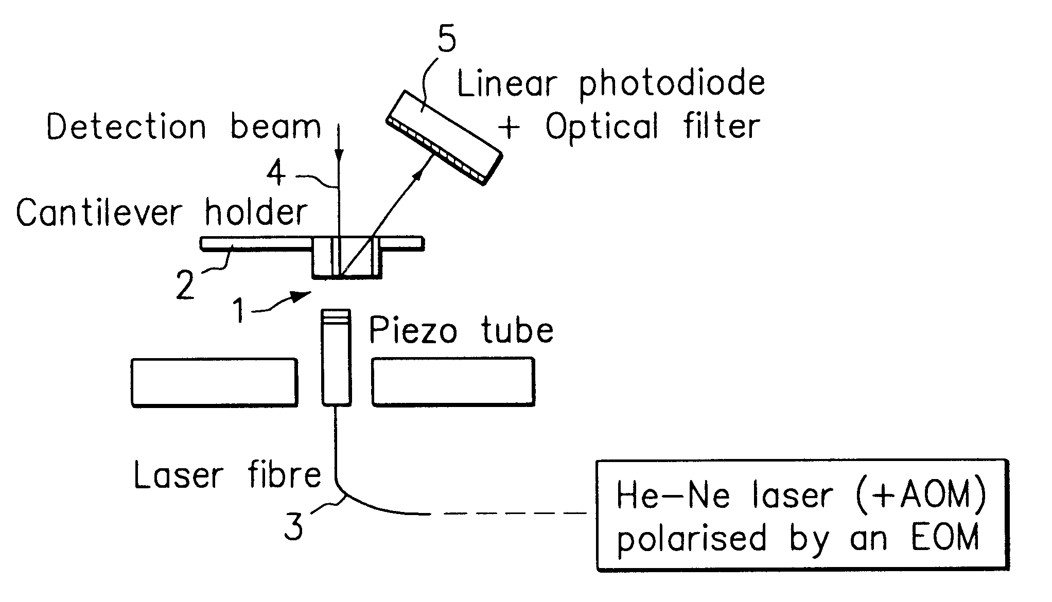
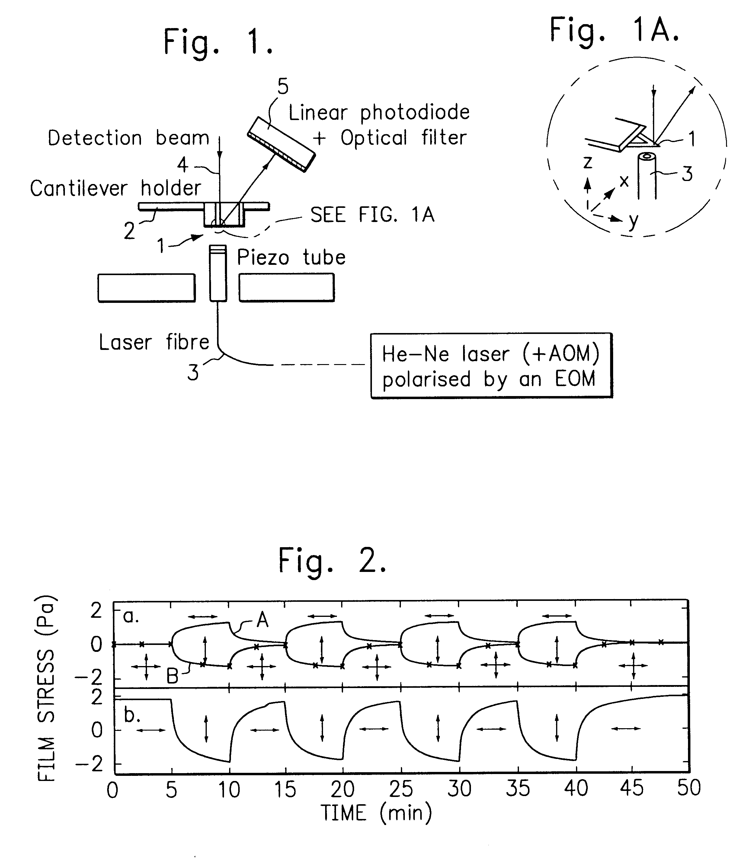
An atomic force microscope typically includes commercially available V-shaped microcantilevers 1. They are fabricated from silicon nitride with typical dimensions 200 .mu.m length, 20 .mu.m width and 0.6 .mu.m thickness. Such microcantilevers 1 are used in an atomic force microscope as a test rig for the present invention. One surface of the microcantilevers 1 is coated with a thin layer, about 20 nm thick, of gold to increase its optical reflectivity. The other surface has a thin amorphous As.sub.50 Se.sub.50 film of thickness about 250 nm evaporated onto it. The microcantilever 1 is then mounted on a cantilever holder 2 of an atomic force microscope. A helium-neon laser, the output of which is square-wave modulated at around 50 Hz by an acousto-optic modulator (AOM) and then polarised in an electro-optic modulator (EOM) is guided via a polarisation preserving fibre 3 and used to illuminate the whole of the surface of the amorphous As.sub.50 Se.sub.50 film.

To monitor movement of th...


PUM


Abstract

An opto-mechanical device is constituted by an optically responsive actuating member in which a mechanical strain occurs in response to changes in its illumination. The actuating member is preferably at least partly formed from a semiconducting glassy matrix such as a chalcogenide glass. Preferably the opto-mechanical device illuminates the actuating member with light which is preferably plane polarized. Preferably it also varies the polarization angle of the plane polarized light to cause a change in the strain generated in the actuating member.

Description

BACKGROUND TO THE INVENTIONWith piezo-electric materials when an electrical field is applied across them a mechanical strain results. This mechanical strain results in expansion or contraction of the piezo-electric material. Accordingly piezo-electric materials can be used to provide mechanical movement in response to an applied electric field. They are particularly used where only small movements are required, for example, on the stages of scanning electron microscopes or in micro-manipulators.STATEMENT OF THE INVENTIONAccording to this invention an opto-mechanical device comprises an optically responsive actuating member in which a mechanical strain occurs in response to changes in its illumination.The optically responsive actuating member is preferably at least partly formed from a semiconducting glassy matrix. Preferably the semiconducting glassy matrix includes a group VI element alone or in combination with at least one element from the same or a different group of the periodi...

Claims


Application Information

Patent Timeline
IPC IPC(8): B25J7/00F03G7/00G02F1/03G02F1/01G01J4/00G01L1/18F04B43/02G01N27/00B81B3/00G12B1/00
CPCB81B3/0032
Inventor ELLIOTT, STEPHEN RICHARDWELLAND, MARK EDWARDKRECMER, PAVEL
Owner CAMBRIDGE UNIV TECH SERVICES LTD
Why Eureka
Try Eureka