
Fiber-optic confocal imaging apparatus and methods of use

a fiber-optic confocal and imaging apparatus technology, applied in the field of optics and microscopy, can solve the problems of lack of spatial resolution, inability to obtain individual cells, and inability to demonstrate the spatial resolution necessary to image cellular structur

Inactive Publication Date: 2002-04-09
BOARD OF RGT THE UNIV OF TEXAS SYST +1
View PDF12 Cites 310 Cited by
  • Summary
  • Abstract
  • Description
  • Claims
  • Application Information

AI Technical Summary

Benefits of technology

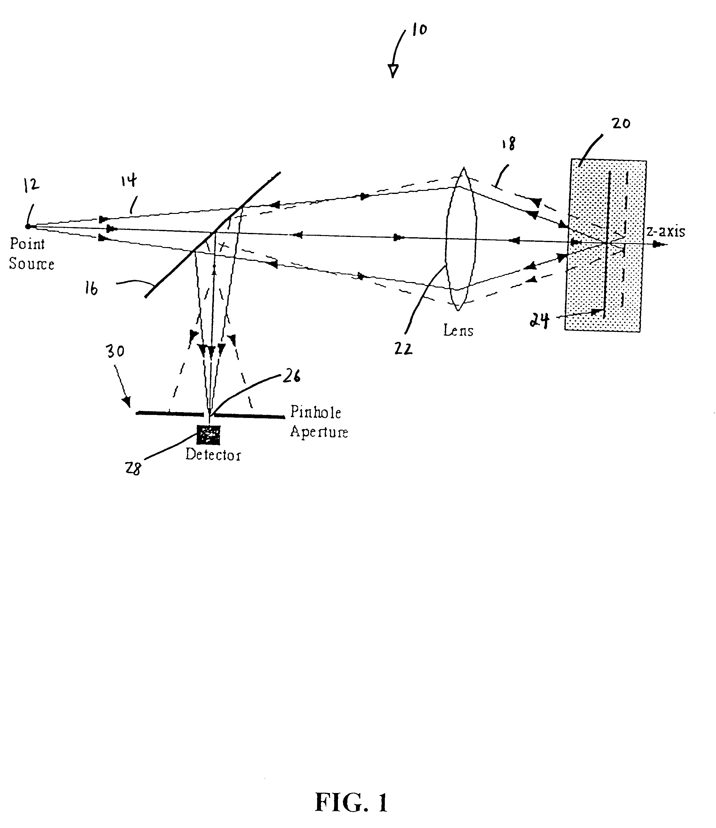
The apparatus may quantitatively analyze a variety of samples, including biological samples. A confocal reflectometer according to the present disclosure may measure the reflected light from a single point. A reflectometer built in accordance with the present disclosure has demonstrated resolution near the diffraction limit and the sensitivity to detect a 0.05 refractive index mismatch under 3 optical depths of scattering.
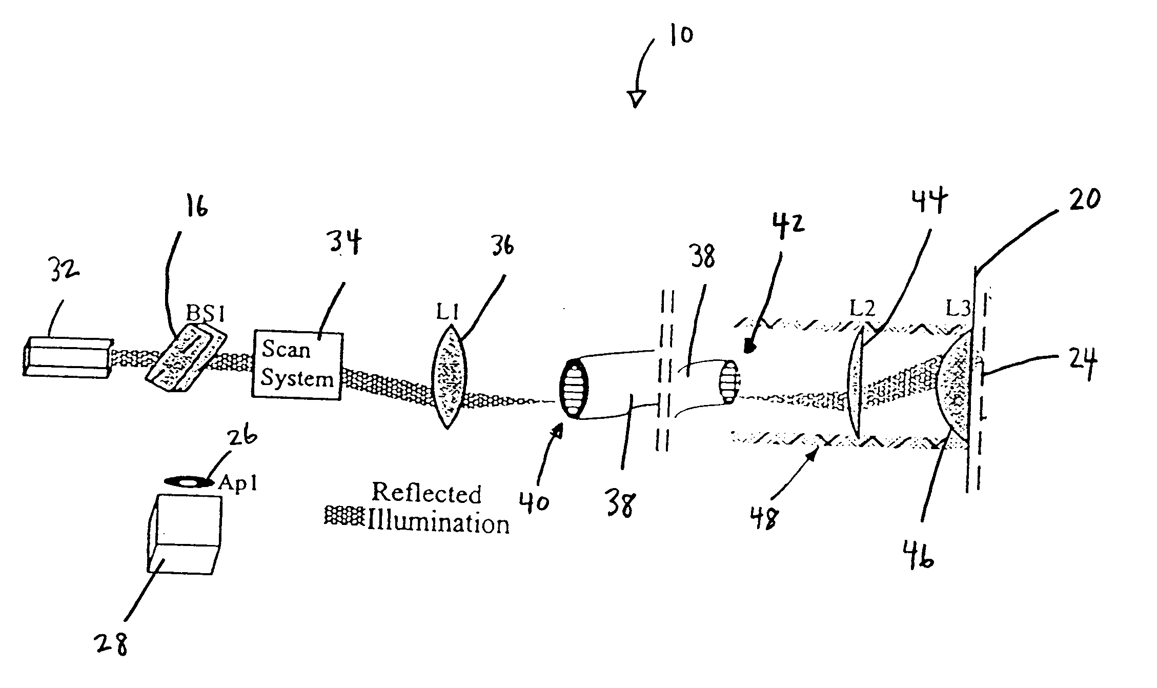
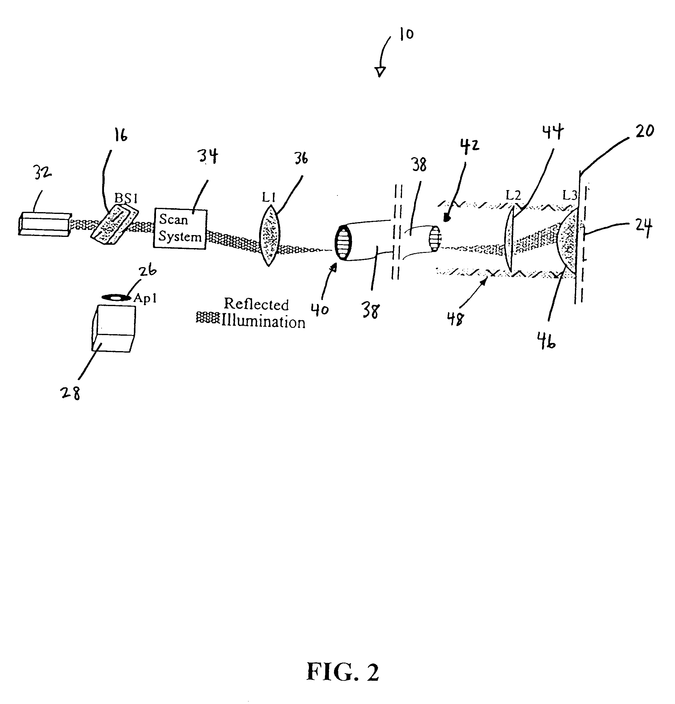
Lenses to incorporate a fiber bundle into a confocal microscope were designed and assembled. An apparatus according to the present disclosure has shown that specular reflection from fiber optic bundle faces may be controlled, and lateral resolution in the range of approximately 5 .mu.m may be achieved. Likewise, an axial resolution of approximately 15 .mu.m has been obtained using the disclosed apparatus.
In other aspects, the coupling lens, the distal end, and the distal index matching agent may make up an endoscope, and the imaging of the sample may include in vivo endoscopic imaging of the sample. The controllably deflecting of the incident radiation may include deflecting the incident radiation in a raster pattern. The method may also include reducing specular reflection from the plurality of fibers with a proximal index matching agent coupled to a proximal end of the plurality of fibers. The sample may include biological tissue. The sample may include an integrated circuit wafer, or portion thereof. The method may also include enhancing contrast of the sample with a contrast agent. The contrast agent may include 5-aminolevulinic acid. The contrast agent may include acetic acid. The acetic acid may consist of about 6% acetic acid. The method may also include modifying a focus depth with a depth translation system in operative relation with the plurality of fibers. The depth translation system may include a suction agent configured to displace at least a portion of the sample by suction. The depth translation system may include a translation stage. The imaging may include cross sectional imaging.

Problems solved by technology

Some researchers have also attempted to use the technique to image scattering tissue such as human skin, however, have not obtained images of individual cells due to the lack of spatial resolution (Yadlowsky et al., 1995).
Thus, while OCT has a high sensitivity, it has not demonstrated the spatial resolution necessary to image cellular structure.
Although the new mode-locked laser gives OCT the potential to achieve the desired resolution, the cost and complexity of these lasers make them impractical for clinical use.
One limitation of this apparatus is the fact that these microscopes are susceptible to misalignment of the disk.
However, the size and configuration of illumination optics prevents use of this system to image tissues within moderately accessible cavities such as the cervix or mouth.
Designing an endoscopic system encompassing a miniature, high speed mechanical scanning system with high spatial resolution is difficult.
This arrangement does avoid the need for a mechanical translation system in the endpiece, however a commercial confocal microscope is expensive and cumbersome, limiting its usefulness as a practical clinical tool.
In addition, the high absorption and scattering of the tissue will not allow the fluorescence excitation and emission light to penetrate the entire depth of the epithelium.
More recently, the same design has been implemented for reflection imaging using white light (Juskaitis et al., 1997) Reflection imaging is capable of penetrating to greater depths; however, the use of a white light source will limit the illumination power available to the system.
A consequence of the limited illumination power will be a limited penetration depth due to loss of signal in scattering tissue.
Although the potential of both in vivo confocal imaging with subcellular resolution and of fiber optic confocal imaging has been demonstrated, there is currently not a system which provides the imaging capabilities required for imaging tissues in vivo within the physical constraints necessary to achieve sufficient resolution and magnification of tissues within a living organism.
Because the fiber bundle requires a difference in index between the individual fiber cores and cladding to function, it is not possible to eliminate or "prevent" the reflection from the fiber face at the proximal end (i.e. the end that light is injected into).
While it is theoretically possible to eliminate the reflections from the distal end by using an oil with an index exactly equal to the index of the fiber cores, it is not practically feasible due to manufacturing limitations and variations.
If the laser has a coherence length greater than the separation between either fiber face and the image plane, the reflections from the fiber faces will interfere with the light reflected from the image plane.
Thus, the unstable speckle pattern they report is a result of interference between one, or both, of the reflections from the fiber faces and the light from the image plane.
However, the fresnel objective lens used in this microscope was not able to achieve the high NA needed for imaging cellular structure.
However, unlike the present invention, this microscope lacks a method for controlling the specular reflections from the faces of the fiber bundle.

Method used


Image

  • Fiber-optic confocal imaging apparatus and methods of use
  • Fiber-optic confocal imaging apparatus and methods of use
  • Fiber-optic confocal imaging apparatus and methods of use

Examples


Embodiment Construction

The presently disclosed methods and apparatus may be applied to the imaging of essentially sample, including any tissue in human or other animal. Such tissues include bone, muscle, ligament, tendon, cartilage, heart, mucus membrane, intestine, gall bladder, pancreas, urethra, lung, brain, prostate, kidney, liver, ovary, breast, skin, stomach, esophagus, head & neck, testicles, colon, cervix, lymphatic system and blood.

The presently disclosed methods and apparatus may be applied to the measurement of tumor resection margins. Tumors may be of essentially any origin and include cancers of the lung, brain, prostate, kidney, liver, ovary, breast, skin, stomach, esophagus, head and neck, testicle, colon, cervix, lymphatic system and / or blood. The presently disclosed methods and apparatus may be of particular use in the field of forensic medicine. In particular, microscopic, 3-dimensional images of wounds may be created. The presently disclosed methods and apparatus may be used in the rese...


PUM


Abstract

An apparatus and methods for fiber optic confocal imaging systems. A plurality of fibers are in communication with a scan system that controllably deflects incident radiation into the fibers in a raster pattern. An index matching agent reduces specular reflections from the fibers.

Description

1. Field of the InventionThe present invention relates generally to the fields of optics and microscopy. More particularly, it concerns apparatus and methods for analyzing samples using fiber-optic confocal imaging techniques.2. Description of Related ArtCurrently, two methods are available for imaging at the cellular level in the body: Optical Coherence Tomography (OCT) (Izatt et al., 1994; Huang et al., 1991; Schmitt et al., 1993; Yadlowsky et al., 1995; Swanson et al., 1993; Schmitt et al., 1994) and confocal imaging (Petroll et al., 1993; Jester et al., 1991; Rajadhyaksha et al., 1995a; Gmitro and Aziz, 1993; Massig et al., 1994; Masters and Thaer, 1994; Giniunas et al., 1993a; 1993b; Delaney et al., 1994).OCT uses interference techniques with low-coherence light sources to select the light coming from a distinct depth (Huang et al., 1991). The basic system uses a Michaelson interferometer with the tissue sample in one arm and a reference mirror in another arm. When the reflecti...

Claims


Application Information

Patent Timeline
IPC IPC(8): A61B5/00A61B1/00A61B1/04
CPCA61B5/0068G02B23/26G02B23/2453A61B5/0084
Inventor RICHARDS-KORTUM, REBECCASMITHPETER, COLIN L.BOWMAN, BRETT S.DESCOUR, MICHAEL R.
Owner BOARD OF RGT THE UNIV OF TEXAS SYST
Learn More