
Embedded wiring structure and method for forming the same

a technology of embedded wiring and wiring trenches, which is applied in the direction of electrical equipment, semiconductor devices, semiconductor/solid-state device details, etc., can solve the problems of inability to accurately position the connection between the via plug and the wiring trench, and the generation of deficiencies in the electrical connection between

Inactive Publication Date: 2002-03-19
NEC ELECTRONICS CORP
View PDF10 Cites 9 Cited by
  • Summary
  • Abstract
  • Description
  • Claims
  • Application Information

AI Technical Summary

Benefits of technology

In accordance with the present invention, since the embedded wiring and the via plug are in contact with each other with a relatively large surface area, deficiencies in electrical connection are hardly generated, and reliability in the electrical connection is significantly higher than that of a conventional connection structure.
Especially effective performance can be obtained in the present invention if the wiring trench and the via plug have the same width.
A low electric resistance metal which may be employed in the metal film in the present invention includes and is not restricted to aluminum and copper. An alloy including one of these metals can be also employed.
The above and other objects, features and advantages of the present invention will be more apparent from the following description.

Problems solved by technology

When, however, the embedded wiring having the single damascenel structure is formed in accordance with the conventional method as described above, an imprecise positional alignment is liable to occur between the via plug and the wiring trench.
As a result, deficiencies in electrical connection may be generated between the via plug and the wiring trench.

Method used


Image

  • Embedded wiring structure and method for forming the same
  • Embedded wiring structure and method for forming the same
  • Embedded wiring structure and method for forming the same

Examples


embodiment 1

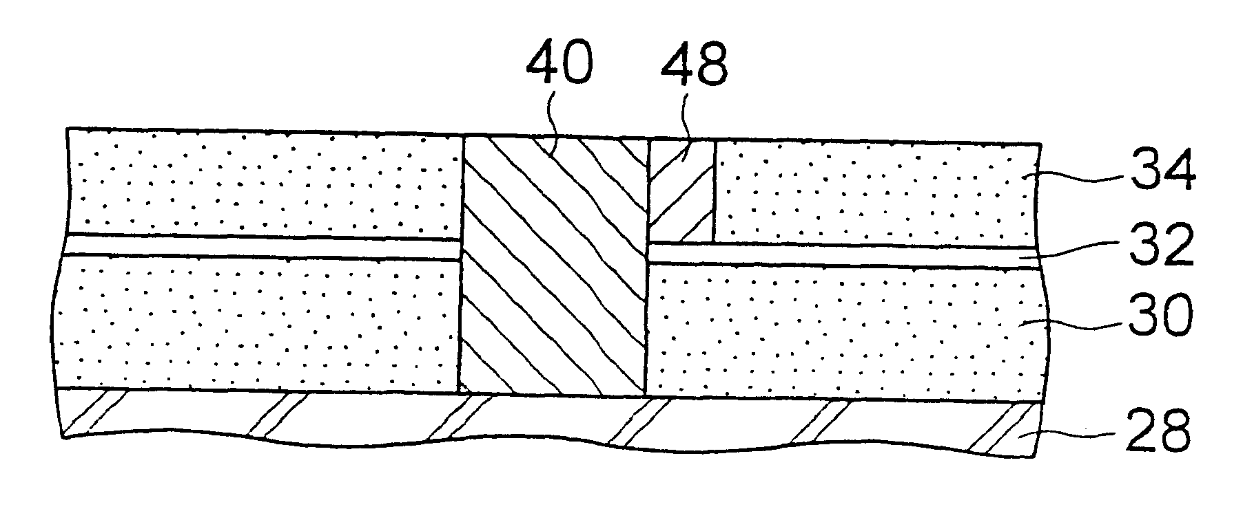
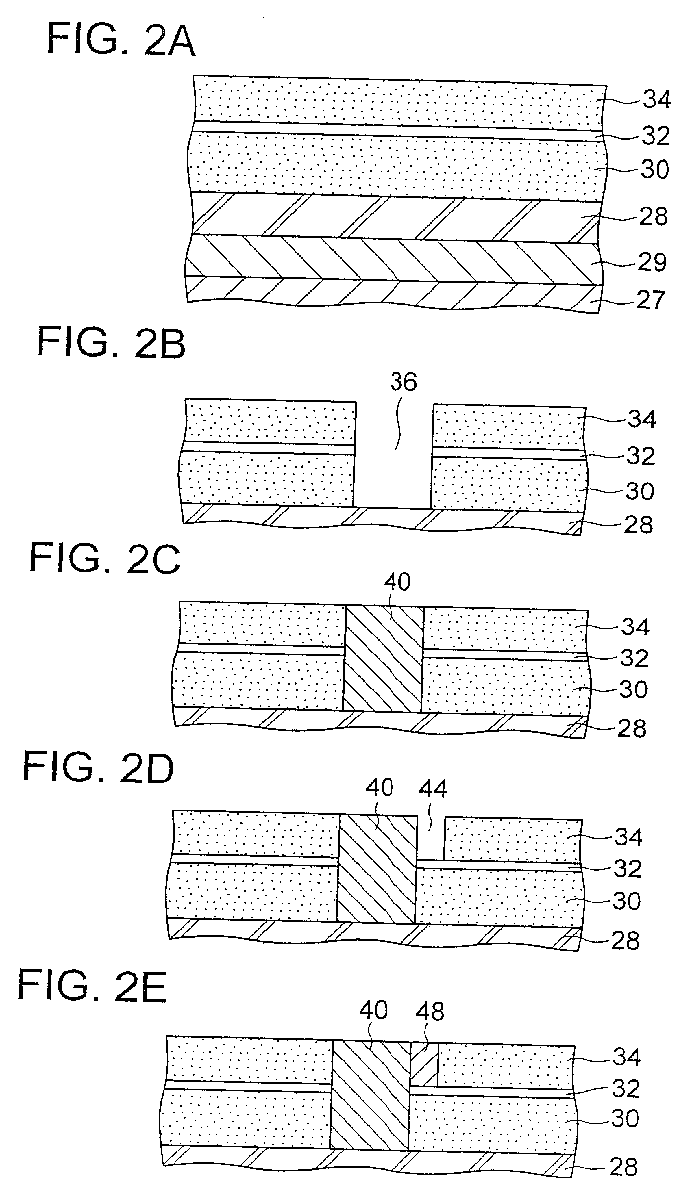
As shown in FIG. 2A, a dielectric film 29, a first wiring layer 28, a first interlayer dielectric film 30, an etch-stop layer 32 made of silicon nitride and a second interlayer dielectric film 34 are sequentially formed on a silicon substrate 27.

Then, a via hole 36 which penetrates the second interlayer dielectric film 34, the etch-stop layer 32 and the first interlayer dielectric film 30 to reach the first wiring layer 28 is formed as shown in FIG. 2B.

The via hole 36 is filled with tungsten (W) formed as a conductive film by sputtering, and during this procedure, a tungsten film is also formed on the surface of the second interlayer dielectric film 34. The tungsten film is then removed by an etch-back to leave a via plug 40 in the via hole 36 as shown in FIG. 2C.

Then, a photoresist film (not shown) is formed on the second interlayer dielectric film 34 and is patterned to form a mask pattern. The dielectric film 34 is selectively etched by using the mask to form a wiring trench 44 a...


PUM


Abstract

Disclosed herein is an embedded wiring structure comprising: a first interlayer dielectric film, an etch-stop layer and a second interlayer dielectric film sequentially formed on a first wiring layer in which a second wiring layer is formed in contact with a wide wall of a via plug. Since, in this structure, the second wiring layer and the via plug are in contact with each other with a relatively large surface area, deficiencies in electrical connection are hardly generated.

Description

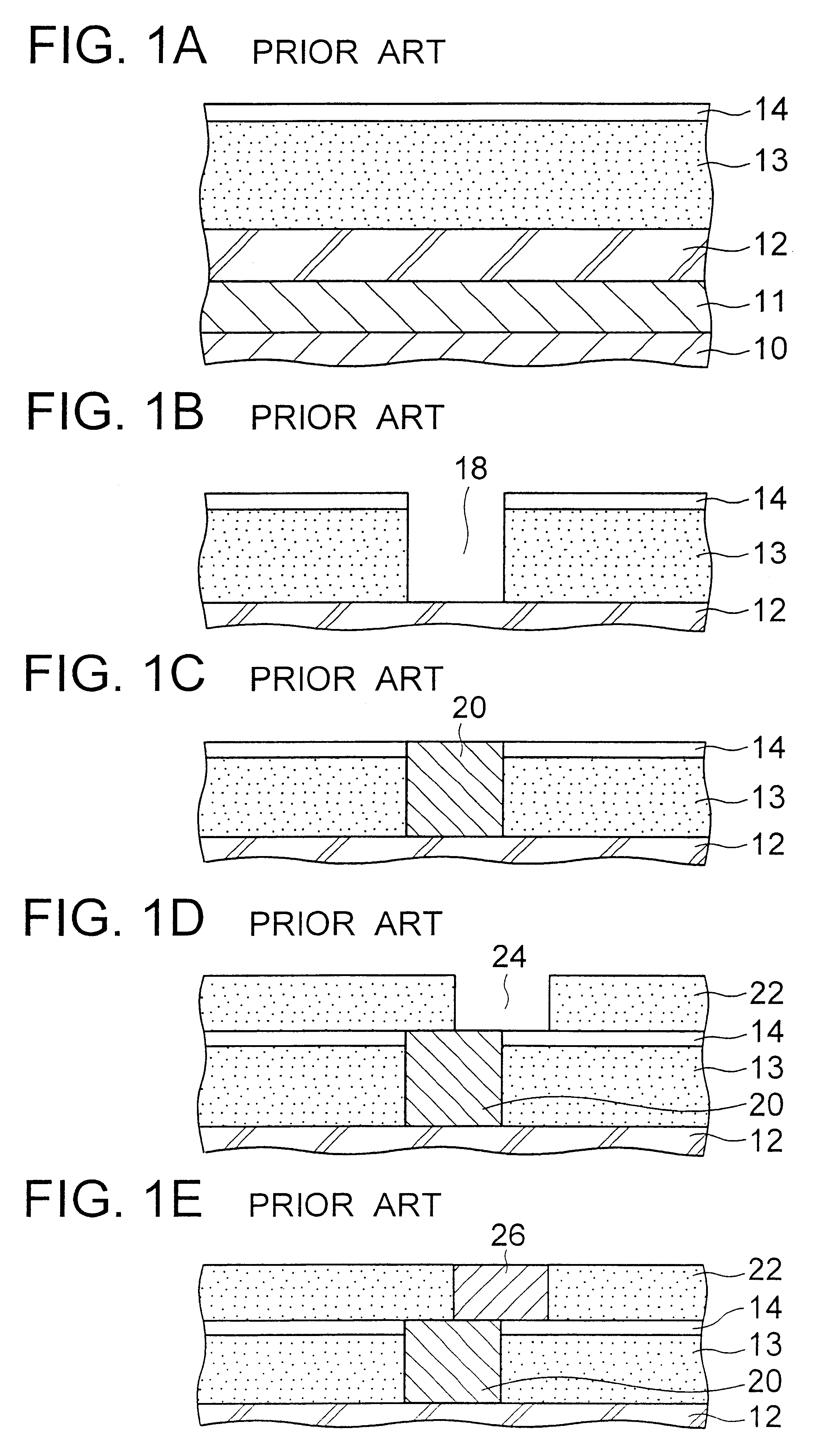
(a) Field of the InventionThe present invention relates to an embedded wiring having a single damascenel structure and a method for forming the same, more in detail to the embedded wiring structure having high reliability in electrical connection and the method for forming the same.(b) Description of the Related ArtWith the demand of miniaturization and high integration of semiconductor devices, wirings of the semiconductor device are made finer and multi-layered.Because of this reason, in place of forming the wiring on a dielectric film, a so-called damascenel process is practiced which forms an embedded metal wiring in a trench of a dielectric film.A conventional method of forming an embedded metal wiring having a single damascenel structure will be described referring to FIGS. 1A to 1E showing sections of a wafer having the single Damasin structure in consecutive steps of fabrication.As shown in FIG. 1A, a dielectric layer 11, a wiring layer 12, a first interlayer dielectric film...

Claims


Application Information

Patent Timeline
Patent Type & Authority Patents(United States)
IPC IPC(8): H01L23/52H01L23/522H01L21/768H01L21/70
CPCH01L21/76807H01L21/76885H01L23/5226H01L2924/0002H01L2924/00H01L23/5283H01L21/768
Inventor KIKUTA, KUNIKO
Owner NEC ELECTRONICS CORP
Learn More