
Safety valve element for battery and battery case cap with safety valve

Inactive Publication Date: 2001-04-03
TOYO KOHAN CO LTD +1
View PDF5 Cites 19 Cited by
  • Summary
  • Abstract
  • Description
  • Claims
  • Application Information

AI Technical Summary

Benefits of technology

Furthermore, according to the present invention, the composite material is produced using a cold pressure welding so that the lowering of the strength of material can be minimized compared to that by the conventional high temperature heat molding method thus realizing a stable operating pressure of the safety valve element for a battery use.
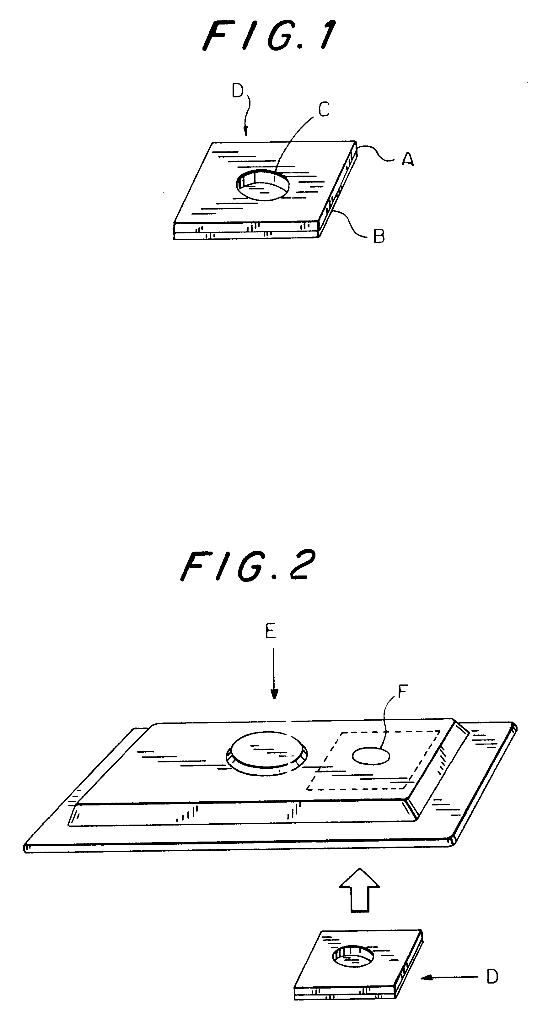
The battery case lid which is provided with the safety valve element may preferably be produced by forming a perforated opening on the metal substrate, pressure welding the metal foil to the metal substrate so as to close the perforated opening and molding the metal substrate into a case lid form.
Accordingly, it is an object of the present invention to provide safety valve elements which rupture precisely at a predetermined pressure in a low pressure range and can be manufactured readily.

Problems solved by technology

Accordingly, during the press working to obtain the extremely thin wall part, fine or minute cracks may occur, and once such cracks occur, the sealability of the vessel is spoiled.
Although the thinned wall part is hardened with such a press working, the hardening does not occur uniformly.
Accordingly, the release valve disclosed in Japanese laid-open publication SHO 63-285859 also suffers from a drawback that even when the thinned wall part is pressed to have a uniform thickness, the thinned wall part does not always rupture at the selected predetermined pressure.
Furthermore, although an etching method has been proposed to make a part of the wall of the battery vessel thin, it is extremely difficult to control the thickness of the thinned wall part after etching and the thinned wall part is apt to suffer from pin holes.
In this manner, with the above-mentioned method, it is extremely difficult to provide the thinned wall part which has a uniform thickness so that especially on the condition that the safety valves are to be operated to release pressure at a low pressure of not more than 30 kgf / cm.sup.2, a reliable reproductivity of the pressure releasing operation cannot be achieved.
Furthermore, these thin metal plates are usually produced by a cold rolling so that they are subjected to hardening by working.
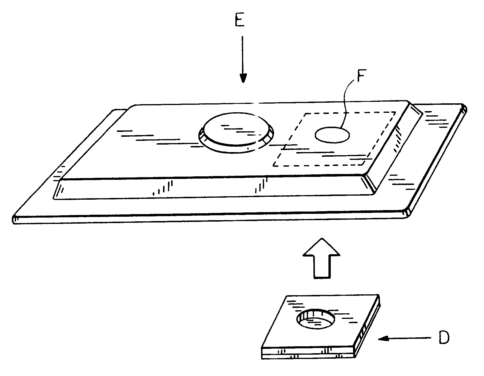
Furthermore, the use of such safety valve elements D having thick metal foil B is not favorable in terms of the manufacturing cost of the batteries.
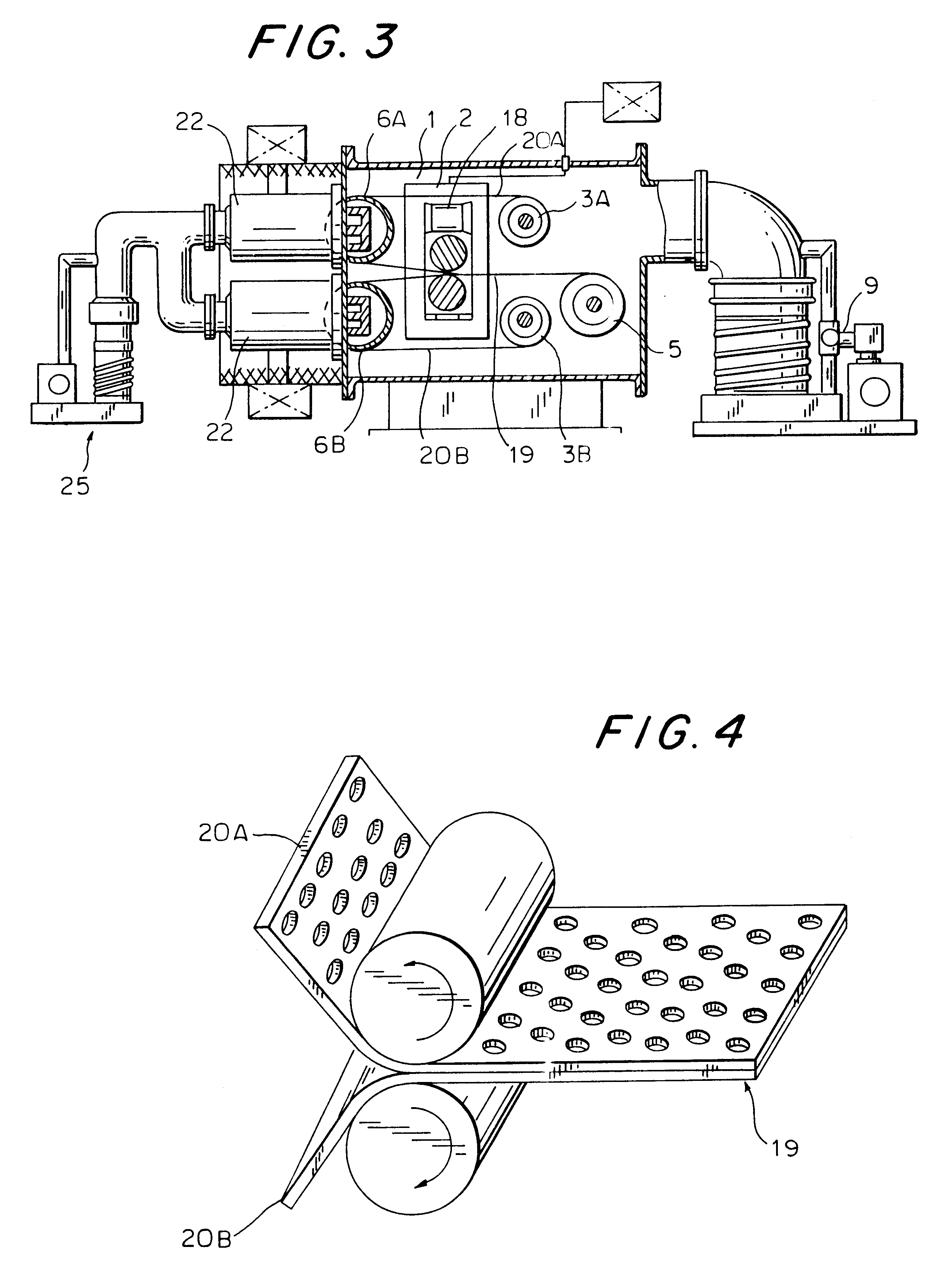
In the case that the frequency is less than 1 MHz, it is difficult for the high frequency power source to assure a stable glow discharge so that a continuous etching is not achieved, while in the case that the frequency is more than 50 MHz, the high frequency power source apts to oscillate so that the power supply system becomes unpreferably complicated.
In the case that the presssure of argon gas is below 1.times.10.sup.-4 Torr, it is difficult to assure the stable glow discharge and a high ion flow is not obtained so that a high speed etching becomes difficult.
Namely, oxygens which are separated from the oxide formed on the surfaces of the metal foil and the metal substrate by etching are again shot to the target so that the efficiency of surface activating treatment is deteriorated.
Namely, although the surface of the plate appears flat at a glance, there are many fine or minute irregularities or indentations in a microscopic level and metals come into contact with each other with an extremely insufficient contact area if pressure is not applied to them and under a conventional cold rolling welding method, a strong welding cannot be obtained even if the surfaces of these metals are sufficiently activated.
It is not desirable that the rolling reduction rate exceeds 30% since such a rolling rate gives rise to an extremely high work hardness.

Method used


Image

  • Safety valve element for battery and battery case cap with safety valve
  • Safety valve element for battery and battery case cap with safety valve
  • Safety valve element for battery and battery case cap with safety valve

Examples


example 2

A multiplicity of circular perforated openings having a diameter of 3 mm were formed on a stainless steel plate rolled by a cold rolling and having a thickness of 60 .mu.m in a lattice pattern by means of a punching press, wherein a pitch between openings was determined to be 10.5 mm. This perforated cold-rolled stainless steel plate and a nickel foil having a thickness of 10 .mu.m were inserted into a vacuum chamber of an argon gas atmosphere having a vacuum level of 1.times.10.sup.-2 Torr so as to provide an etching of approximately 500 angstrom on one surface of the cold-rolled and perforated stainless steel plate and an etching of approximately 500 angstrom on the corresponding one surface of the nickel foil by the magnetron sputtering method. Subsequently, the etched surfaces of the cold-rolled and perforated stainless steel plate and the nickel foil were laminated and both plate and foil were pressure welded by a cold rolling at a room temperature and with a rolling reduction ...

example 3

A multiplicity of circular perforated openings having a diameter of 3 mm were formed on the cold rolled steel plate having a thickness of 90 .mu.m in a zigzaging pattern by means of a punching press, wherein a pitch between openings was determined to be 10.5 mm. A nickel plating having a thickness of 2 .mu.m was applied to both surfaces of the cold rolled steel plate in the same manner as that of the example 1.

This nickel-plated and perforated steel plate and a copper foil having a thickness of 10 .mu.m were inserted into a vacuum chamber of an argon gas atmosphere having a vacuum level of 2.times.10.sup.-3 Torr so as to provide an etching of approximately 500 angstrom on one surface of the nickel plated steel plate and an etching of approximately 500 angstrom on the corresponding one surface of the copper foil by the magnetron sputtering method. Subsequently, the etched surfaces of the nickel plated steel plate and the copper foil were laminated and pressure welded by a cold rollin...


PUM


Abstract

A safety valve element for battery use which ruptures at a stable pressure range so as to release the inner pressure of the battery is disclosed. The safety valve element for battery use comprises a metal substrate which is provided with a perforated opening and a metal foil laminated on the metal substrate so as to close the perforated opening. A battery which is provided with such a safety valve is also disclosed. A battery case provided with such a safety valve is also disclosed. The battery and the battery case lid is produced by forming the perforated opening in the metal substrate, pressure welding the metal foil to the metal substrate and molding the clad material into a form of the battery case lid.

Description

The present invention relates to especially safety valve elements for battery use, battery case lids provided with safety valves and batteries produced by employing such safety valve elements and battery case lids.DESCRIPTION OF RELATED ARTConventionally, batteries which use an alkali metal such as lithium, sodium or potassium as an active material on negative electrode thereof sometimes suffer from rupture when the pressure in the batteries becomes abnormally elevated. To prevent the occurrence of such a rupture, safety valves which can release the pressure outside when the pressure in the battery reaches an excessive level have been requested and accordingly various safety valves having different mechanisms have been proposed. To assure the safety in which even when the battery ruptures by a chance, broken pieces or contents of the battery do not scatter outside and cause no damage especially to personnel, the batteries must be operated at a low pressure of not more than 30 kgf / cm...

Claims


Application Information

Patent Timeline
IPC IPC(8): H01M2/12H01M2/10
CPCH01M2/1241Y02E60/10H01M50/3425
Inventor TAKADA, AKIYOSHITAKAGI, AKIRASAIJO, KINJIYOSHIDA, KAZUOYOSHIMOTO, NOBUYUKIISOBE, YOSHIHIKO
Owner TOYO KOHAN CO LTD
Learn More