Micro-circuit system with array of functionalized micro-electrodes
a micro-circuit system and array technology, applied in the field of micro-circuit systems, can solve the problems of inability to meet the needs of conventional diagnostic techniques, lack of specificity or reproducibility, time-consuming and inconvenient use,
- Summary
- Abstract
- Description
- Claims
- Application Information
AI Technical Summary
Problems solved by technology
Method used
Image
Examples
example 3
The previous two Examples were concerned with micro-readers suitable for a substantially transparent micro-circuit, such as an array of indium tin oxide micro-electrodes. However, the micro-circuit of the present invention can also include an array of gold micro-electrodes which are not transparent. Such an array requires a different system for the detection of light emitted from the fluorescent moieties on the complementary probes.
One exemplary embodiment of a micro-reader suitable for an array of micro-electrodes is shown in FIG. 16. A micro-reader 130 includes a light source 132 of any suitable type including, but not limited to, a laser, a monochromator, a mercury arc lamp or a Xenon lamp. If a mercury arc lamp or a Xenon lamp is used, a suitable filter is preferably used (not shown). Light passes from light source 132 through a beam splitter 134 and is then focused onto a single micro-electrode 136 by a micro-lens 138, which is part of a micro-lens array 140 as shown. As light ...
example 4
Examples 1-3 showed micro-readers which could read a single micro-circuit at a time. However, it is often desirable to be able to read a plurality of micro-circuits relatively rapidly. Furthermore, it would be desirable to be able to read a micro-circuit regardless of the type of micro-electrode employed. FIG. 17 shows an exemplary illustration of a multiplexed micro-circuit reader which can both collect data from a plurality of micro-circuits and which is not limited to substantially transparent arrays of micro-electrodes.
A multiplexed micro-circuit reader 148 includes a plurality of collection heads 150 (four are shown), similar to the collection head shown in FIG. 16. Each collection head 150 is positioned above a separate micro-circuit 152. Each micro-circuit 152 is supported by a separate plate supporting assembly 154.
Each collection head 150 is connected by a respective set of input optical fibers 156 to an optical coupler 158. Optical coupler 158 has a single set of output op...
example 1
Nucleic Acid Hybridization
The method described herein is intended as an illustration of a nucleic acid hybridization and is not meant to be limiting in any way. For the purposes of description, the nucleic acids discussed herein are oligodeoxynucleotides or fragments of DNA, it being understood that other types of nucleic acids or nucleic acid chains could be used in place of oligodeoxynucleotides.
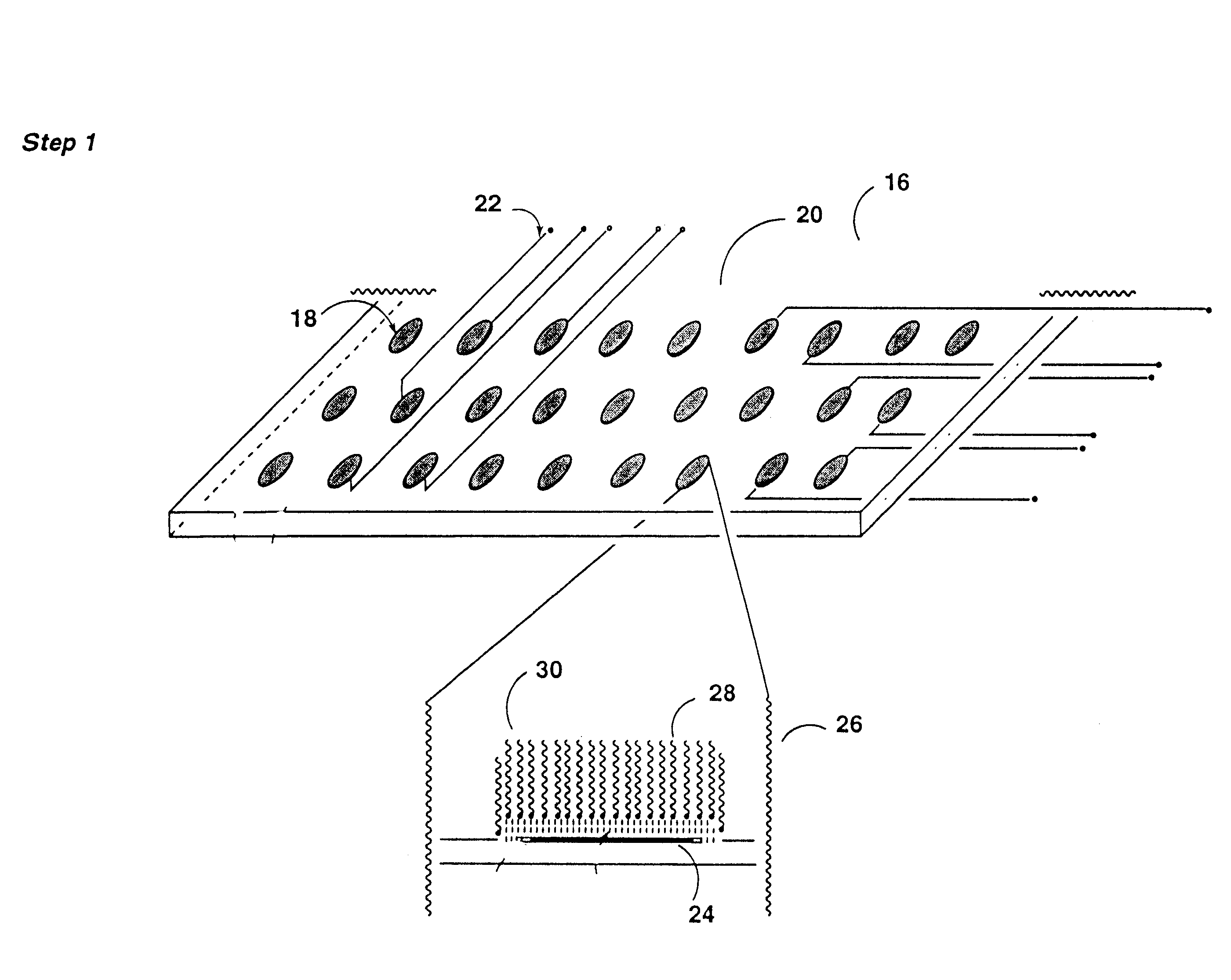
As a first step in the hybridization procedure, a micro-circuit is prepared as described previously. Briefly, different target DNA fragments are preferably attached to each individual micro-electrode, although a plurality of micro-electrodes could have DNA fragments of identical nucleotide sequence attached if desired. The attachment process can either be a one-step process, in which a functional group on the DNA fragment reacts directly with the surface of the micro-electrode, or a two step process. In the two-step process, a spacer molecule is attached to the surface of the micro-electro...
PUM
| Property | Measurement | Unit |
|---|---|---|
| size | aaaaa | aaaaa |
| size | aaaaa | aaaaa |
| size | aaaaa | aaaaa |
Abstract
Description
Claims
Application Information
 - R&D
- Intellectual Property
- Life Sciences
- Materials
- Tech Scout
- Unparalleled Data Quality
- Higher Quality Content
- 60% Fewer Hallucinations
Browse by: Latest US Patents, China's latest patents, Technical Efficacy Thesaurus, Application Domain, Technology Topic, Popular Technical Reports.
© 2025 PatSnap. All rights reserved.Legal|Privacy policy|Modern Slavery Act Transparency Statement|Sitemap|About US| Contact US: help@patsnap.com


