Eureka AIR delivers breakthrough ideas for toughest innovation challenges, trusted by R&D personnel around the world.

Method for fabricating composite pressure vessels

a pressure vessel and composite technology, applied in vessel construction details, machines/engines, other domestic articles, etc., can solve the problems of limited temperature capability, lack of extended durability, unsatisfactory finished product aesthetics,

Inactive Publication Date: 2001-01-09
FLECK CONTROLS +1
View PDF56 Cites 53 Cited by
  • Summary
  • Abstract
  • Description
  • Claims
  • Application Information

AI Technical Summary

Benefits of technology

It is therefore a broad object of this invention to provide an improved process for fabricating a composite pressure vessel.
It is more particular an object of this invention to provide such an improved process which enjoys advantages including, as opposed to prior art processes of fabricating composite pressure vessels: better control over reinforcement / matrix ratio, scrap materials which can be effectively recycled, diminished regulation issues caused by emissions, higher processing speeds for the winding (or alternatives to winding) and curing steps, substantial labor savings due to less material handling, floor space reduction, susceptibility to automation, a safer environment for employees, simplification of processing lines and of material storage and handling, faster changeover times, faster startups, lower training costs, lower energy costs, etc.
In another aspect, it is an object of this invention to provide a process for fabricating composite pressure vessels which, in use, enjoys long term performance at least as good as that of traditional pressure vessels.
In still yet another aspect, it is an object of this invention to provide high quality composite pressure vessels which have improved durability, impact resistance and corrosion resistance as well as higher temperature and pressure handling characteristics and which also have good machinability attributes and can therefore readily be welded, cut, drilled, threaded, stamped or the like as may be desired to produce a high quality finished product.

Problems solved by technology

However, these resin systems have well known drawbacks which may include their limited temperature capabilities, unsatisfactory finished product aesthetics, lack of extended durability, lack of appropriateness for recycling and manufacturing related issues such as downtime due to clean-up and material handling costs.
Further, there are environmental concerns arising from worker exposure to vapor, overspray, emissions, etc. encountered during the fabrication processes.
Some engineered thermoset resins improve performance through higher temperature capability, but unacceptable material costs are associated with them.
In addition, because of the materials and processes employed, composite pressure vessels prepared according to the prior art processes inherently have residual and significant internal stresses which, along with certain temperature sensitive incompatibilities of the materials, limit the pressure and temperature ranges in which the pressure vessels find use.
Thus, increasing performance demands, environmental issues, manufacturing issues and new market opportunities have emphasized the limitations of the use of thermoset resins in the manufacture of composite pressure vessels.

Method used


Image

  • Method for fabricating composite pressure vessels
  • Method for fabricating composite pressure vessels
  • Method for fabricating composite pressure vessels

Examples


Embodiment Construction

)

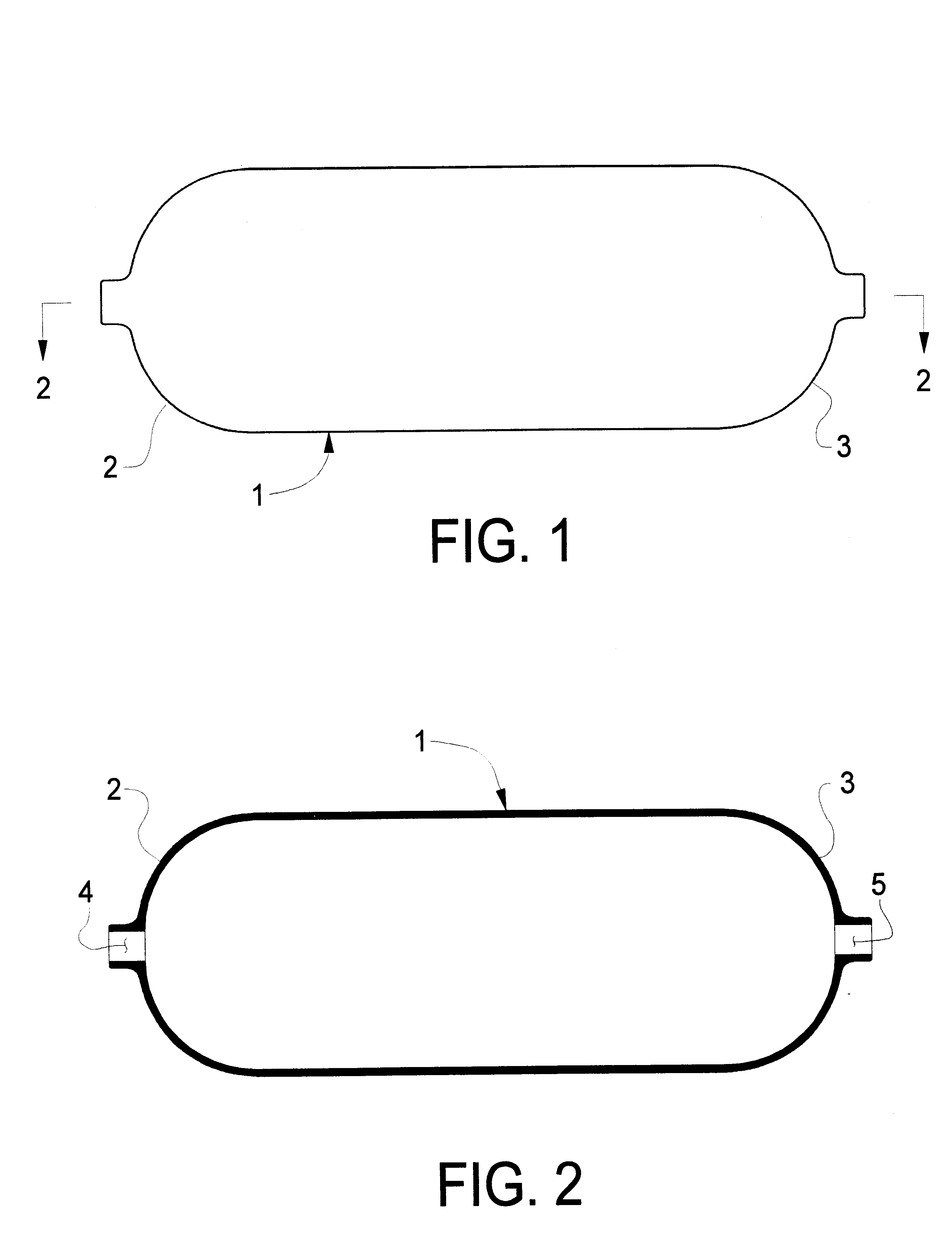
Referring first to FIGS. 1 and 2, there is shown a thermoplastic liner / mandrel 1 for a composite pressure vessel to be fabricated according to a first inventive embodiment. In the exemplary embodiment, the liner / mandrel 1 is a generally elongated preformed structure terminating at each end in a dome shape 2, 3 having a central, axial opening 4, 5. Thermoplastic liner 1 may, for example, be made of polypropylene, polyethylene, polybutylene terephthalate, polyethylene terephthalate or fiber (e.g., fiberglass) impregnated polypropylene, polyethylene, polybutylene terephthalate or polyethylene terephthalate or another thermoplastic material with appropriate characteristics and can be prepared by any suitable conventional process such as molding a combination of chopped fiber, directional, woven and / or knitted fiber fabric sewn or welded together in the shape of the vessel and commingled with thermoplastic material.

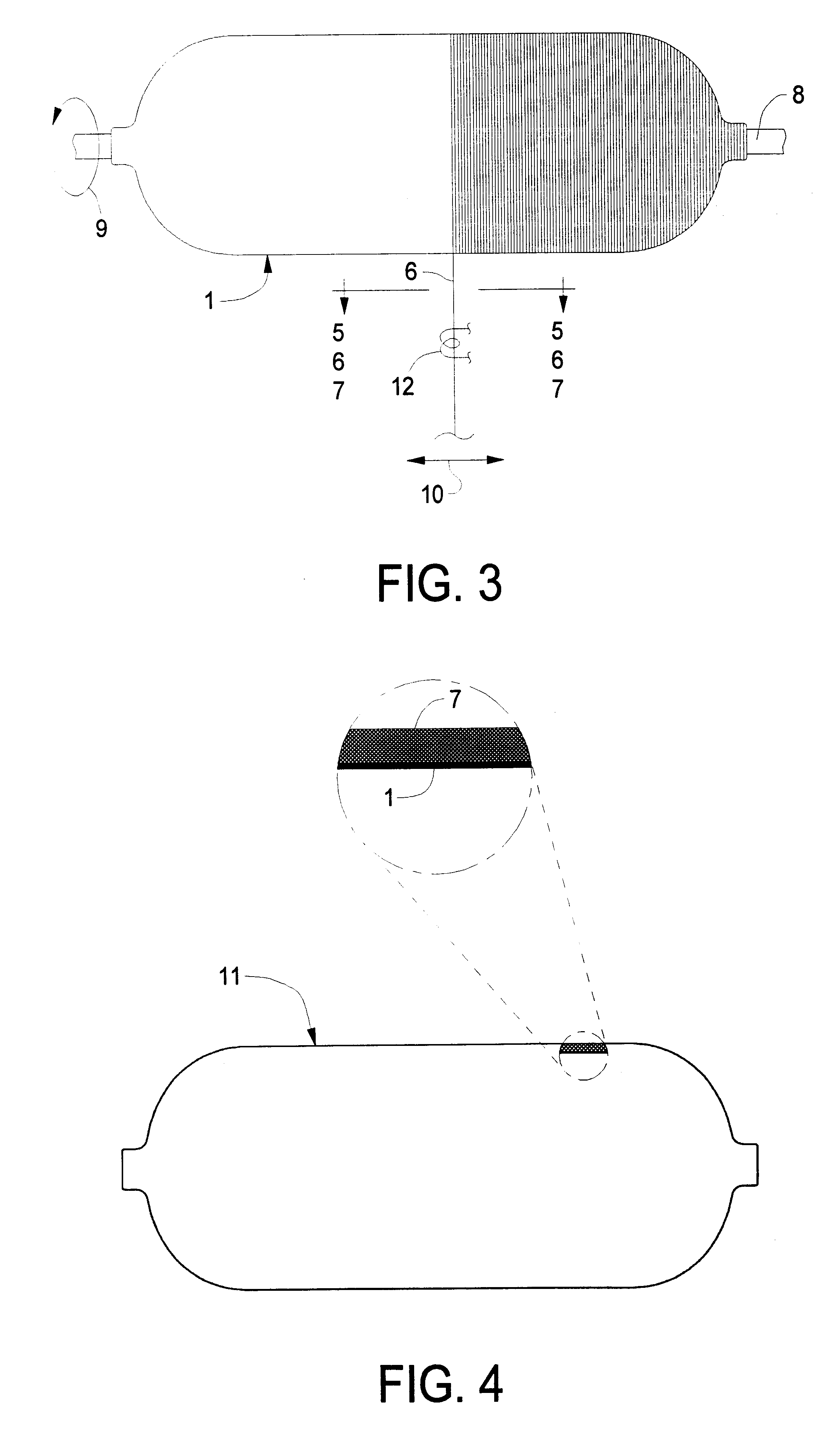
As shown in FIG. 3, a filament, roving, yarn or tape 6 of fiber (e.g., f...


PUM

PropertyMeasurementUnit
Forceaaaaaaaaaa
Pressureaaaaaaaaaa
Mechanical propertiesaaaaaaaaaa

Abstract

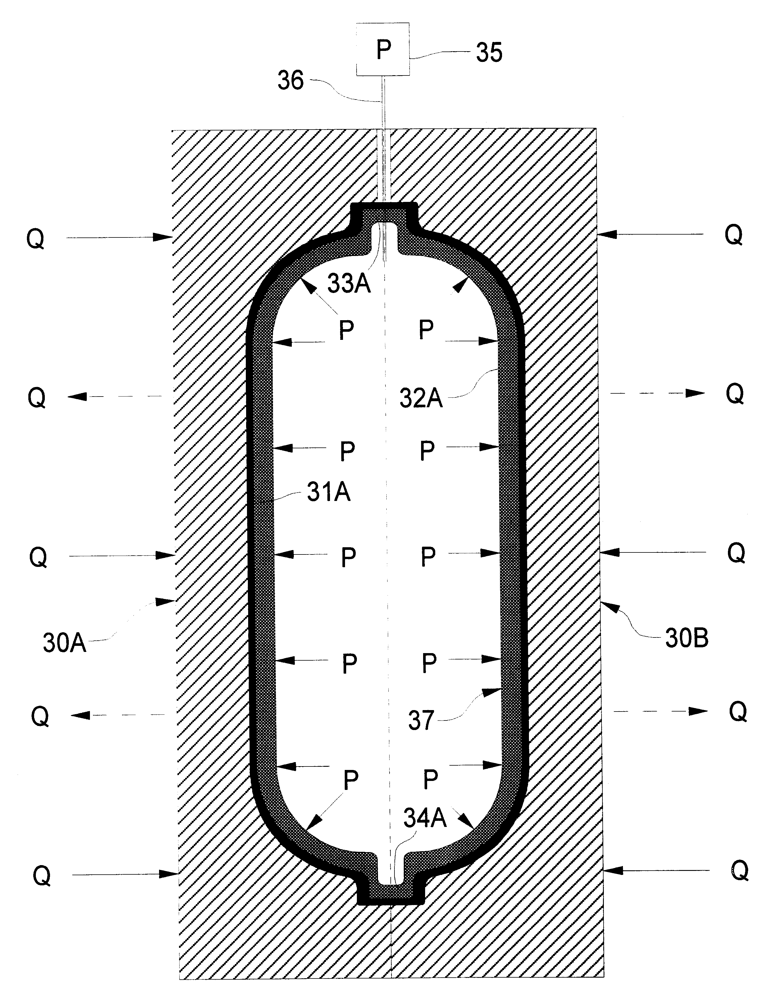
A process for fabricating a composite vessel includes the steps of: A) preforming (e.g., by winding fiber and at least one thermoplastic substance onto a thermoplastic liner) a thermoplastic shell which has at least one opening for access to the interior; B) extruding a circular cross section of a fluid parison of thermoplastic material (which preferably is chosen to have a melting point lower than that of the thermoplastic shell) into the interior of the thermoplastic shell through the opening; C) in a mold, applying at least one force (such as gas under pressure) which tends to urge the fluid parison toward the interior walls of the thermoplastic shell (which may be preheated prior to introduction into the mold) such that the fluid parison imparts heat to the thermoplastic shell; D) continuing step C) until the thermoplastic shell and the fluid parison consolidate to form a composite vessel; E) cooling the vessel until it is solidified; and F) removing the vessel from the mold. For some composite vessels, prior to step C), an insert may be introduced into the interior of the parison and positioned in alignment with the opening in the thermoplastic shell such that the insert is rendered integral with the composite vessel during step D). Suitable thermoplastic materials include polyethylene, polypropylene, polybutylene terephthalate and polyethylene terephthalate. The resulting composite vessel exhibits superior mechanical and aesthetic properties.

Description

This invention relates to the art of fabricating pressure vessels and, more particularly, to improved methods for fabricating composite pressure vessels and to composite pressure vessels made in accordance with the improved methods.Pressure vessels, such as hot water heaters, boilers, pressurized gas tanks and the like, have traditionally been fabricated from metal such as steel. However, in recent years, the use of composite pressure vessels has become more prevalent. These composite pressure vessels have typically been fabricated by a filament winding process which utilizes thermoset plastic resins such as epoxies, polyesters and vinylesters. Briefly, this technology is the process of impregnating dry fibers, such as fiberglass strands, with catalyzed resin prior to application to a mandrel. Preimpregnated fibers ("prepreg") may also be used. The mandrel and applied composite are then cured, at ambient temperature or with heat, to set-up the laminate and obtain a hard resin and fi...

Claims


Application Information

Patent Timeline
IPC IPC(8): B29C53/60B29C53/00B29C70/04B29C49/24B29C70/44B29C49/42B29C49/44B29C70/34B29C53/66B29C49/00
CPCB29C49/24B29C49/44B29C53/602B29C70/342B29C70/446B29C49/00B29C53/66B29C2049/2422B29K2101/12B29K2701/12B29L2031/7156F17C2209/2154B29C70/44
Inventor MURPHY, JAMES C.BOYCE, GERALD S.COECKELBERGS, ERIK
Owner FLECK CONTROLS
Why Eureka
Eureka Blog
Learn More