Temperature control system for test heads
a temperature control system and test head technology, applied in the field of test heads, can solve the problems of high failure rate of cpu, no cooling device provided for cooling dut, high temperature within the chip body during operation, etc., and achieve the effect of improving the passing rate and large energy consumption
- Summary
- Abstract
- Description
- Claims
- Application Information
AI Technical Summary
Benefits of technology
Problems solved by technology
Method used
Image

Examples
experiment 1
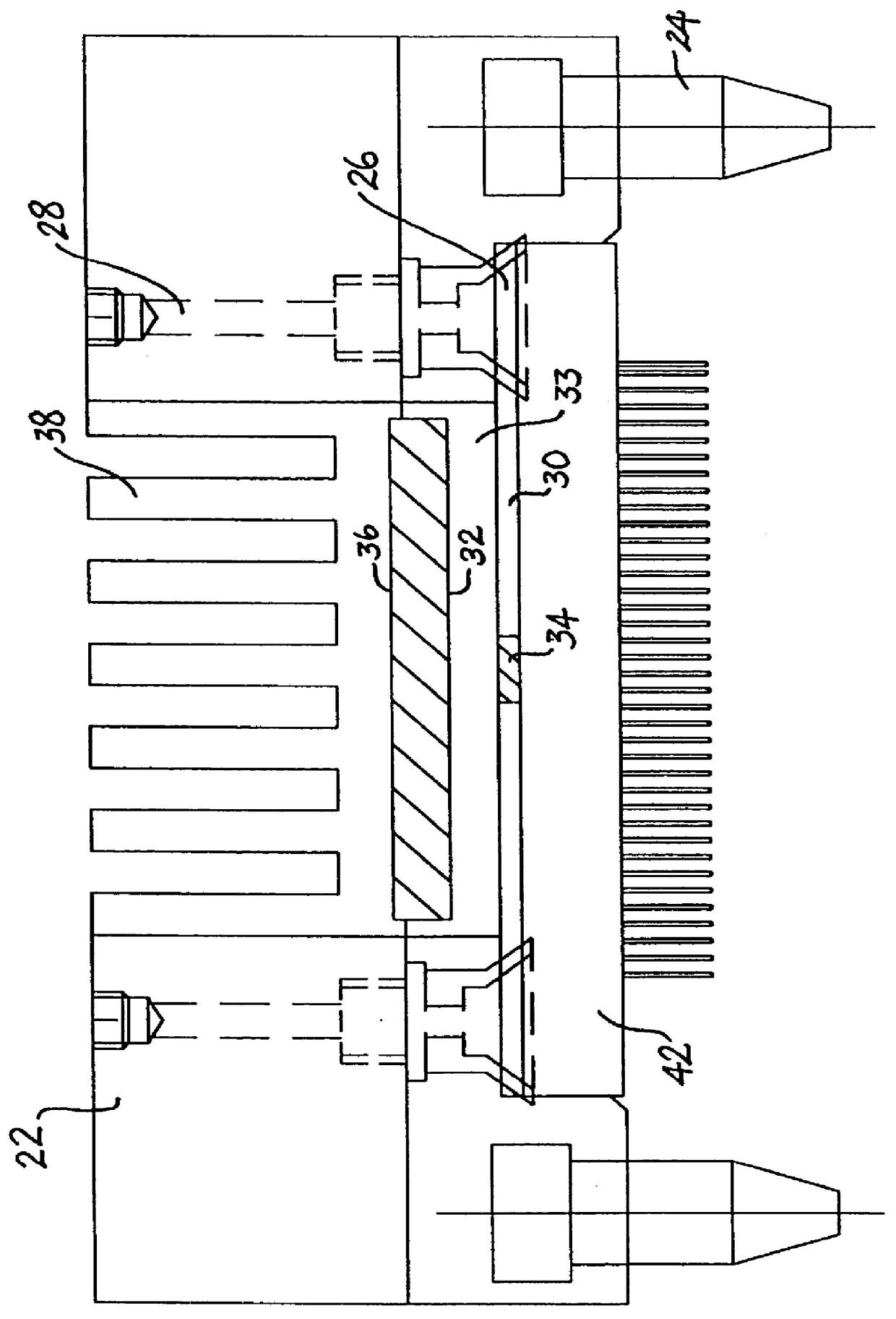
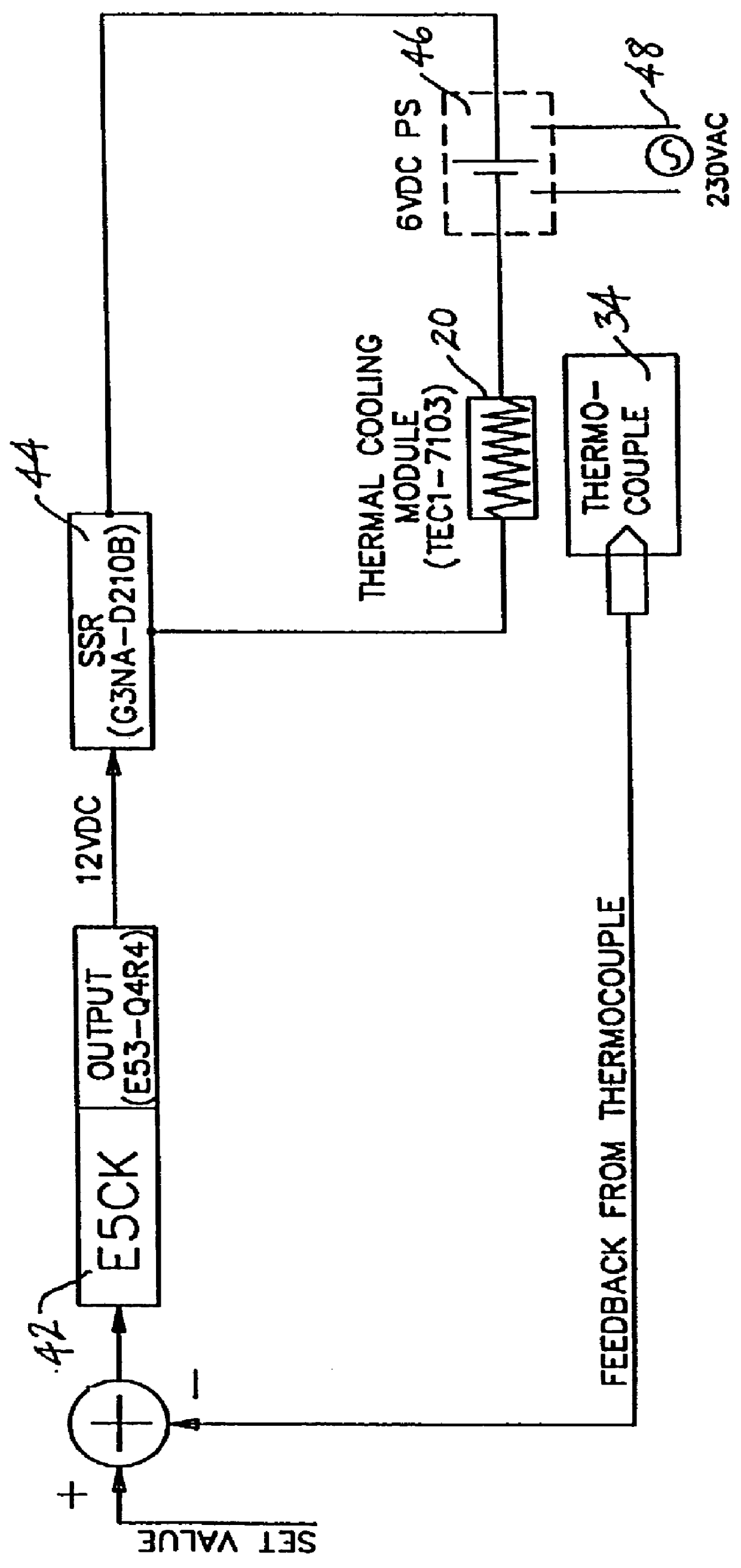
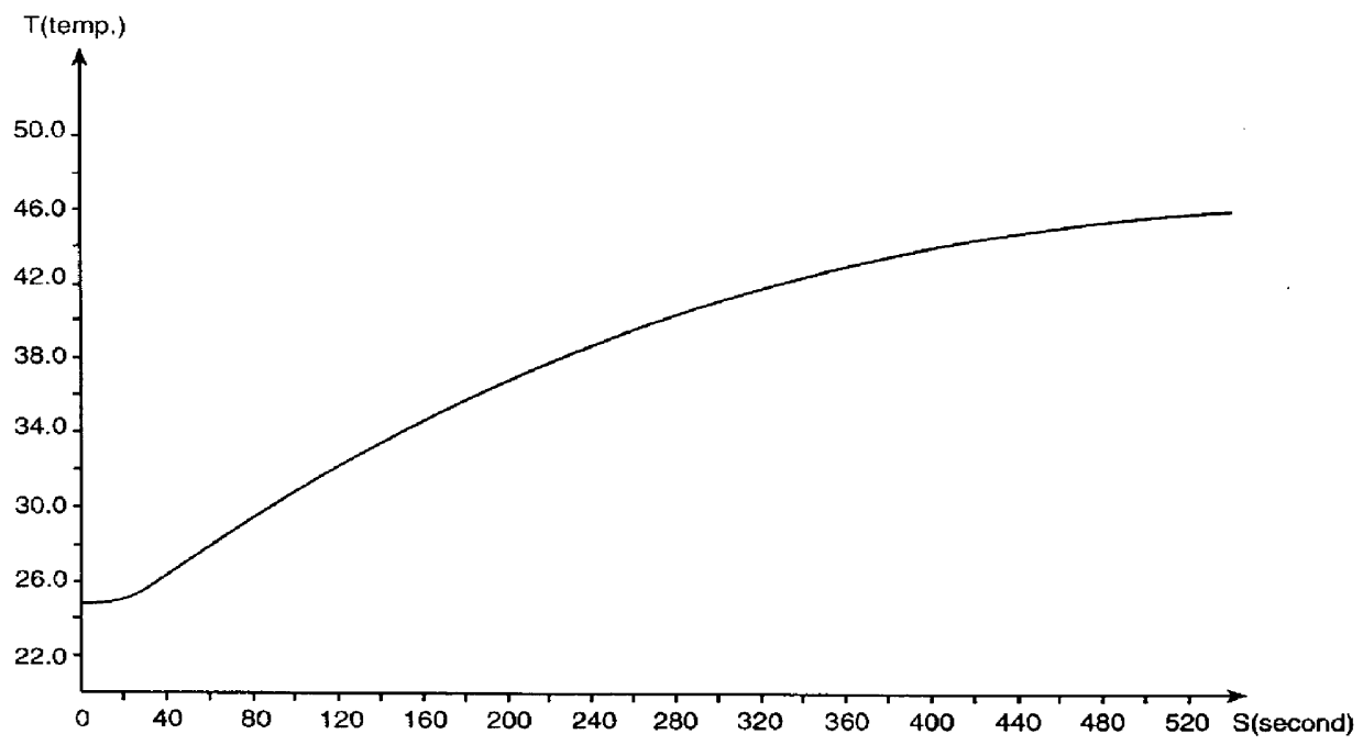
Experiments were first performed to confirm that the cooling module used (TEC1-7103) has the required cooling capacity. The system was set up as shown in FIG. 1, except that an interface panel was not used, and the heating plate was attached via the suction cups directly adjacent the cooling module and the thermosensor. The heat plate was first heated up at a constant 4.4 W (shown in FIG. 3A) without any cooling action. Results of the temperature change of the heater plate are shown in FIG. 3B. Because of the system thermal inertia, the heat plate temperature started a steep rise from ambient temperature several seconds after the heater was switched on. The rate of increases was approximately 0.085.degree. C. per second after the initial period. When the heat plate temperature reached 49.degree. C. 560 seconds later, the temperature was stabilized and the rate of increase was reduced to 0.01.degree. C. per second due to an increased thermal dissipation capacity from the heat plate t...
experiment 2
This set of experiments were conducted to determine how precisely the temperature of the DUT may be maintained when the power consumption of the DUT fluctuates widely. This stimulates actual testing conditions of a test handler as the IC device is switched on and off, and is also subjected to functional tests which require variable output. Again, the heater plate is attached directly to the cooling module without the interface panel. The controller is set at ambient temperature of 23.8.degree. C. before the heating plate was activated.
FIG. 6B shows the temperature change of the heating plate corresponding to the power output shown in FIG. 6A. This experiment simulates conditions at the start of the IC testing procedure. At the beginning of this experiment, a state of thermal balance is maintained at ambient temperature, with no power supplied to the heating plate. When a constant 4.4 W output is supplied to the heating plate at 20 seconds, the temperature increased by 1.5.degree. C....
experiment 3
This set of experiment shows how the system responded to power pulses applied to the heating plate. FIG. 8 shows results of an experiment which simulated the starting of the testing, in which a 50V, 4.4 W 40-second power pulse is applied to the heater. This is followed by additional 50V 40-second pulses at 40-second intervals. The system was initially controlled at ambient temperature of 23.6.degree. C., and when the power pulse was switched on, the initial ambient thermal balance is interrupted and the temperature of the heater plate rose to 25.1.degree. C., which is 1.5.degree. C. higher than the pre-determined value. At the end of the 40 second power pulse, the temperature of the heater plate was slowly reduced to 23.1.degree. C., and continued to fluctuate between 0.8.degree. C. higher or lower than the ambient temperature in response to the power pulses.
FIG. 9 shows the results when the 50V, 4.4 W power pulses were administered in 10-second durations with 10-second intervals be...
PUM
 Abstract
Description
Claims
Application Information
 - R&D
- Intellectual Property
- Life Sciences
- Materials
- Tech Scout
- Unparalleled Data Quality
- Higher Quality Content
- 60% Fewer Hallucinations
Browse by: Latest US Patents, China's latest patents, Technical Efficacy Thesaurus, Application Domain, Technology Topic, Popular Technical Reports.
© 2025 PatSnap. All rights reserved.Legal|Privacy policy|Modern Slavery Act Transparency Statement|Sitemap|About US| Contact US: help@patsnap.com