Fuel cell gas management system

Inactive Publication Date: 2000-01-11
EMPRISE TECH ASSOC
View PDF12 Cites 457 Cited by
  • Summary
  • Abstract
  • Description
  • Claims
  • Application Information

AI Technical Summary

Benefits of technology

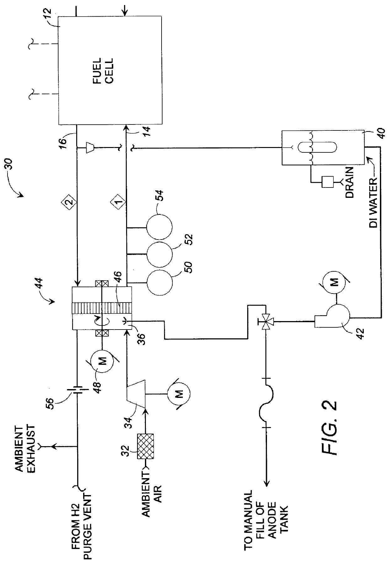
As a further refinement to the invention, the size of the openings in the enthalpy wheel can be chosen to selectively filter out nitrogen and other components of the cathode inlet airstream, thereby increasing the partial pressure of oxygen in the inlet airstream to increase fuel cell efficiency. Alternatively, two or more porous wheels can be provided in series, having opening sizes to selectively filter out various components from the cathode inlet and / or exhaust streams.
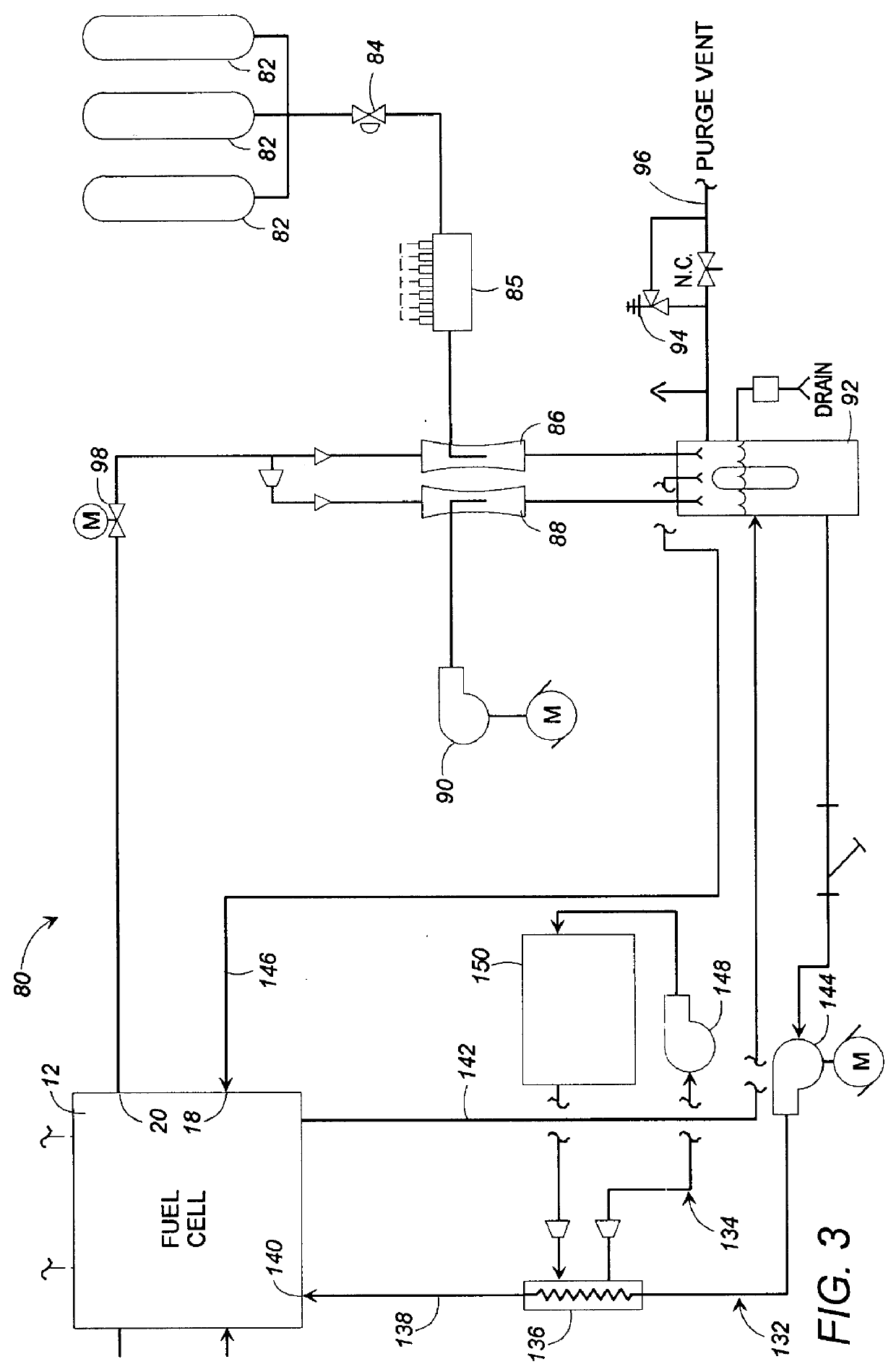
The anode humidity retention system of the present invention preferably comprises one or more eductors or other means for recirculating the anode exhaust stream to the anode inlet. By mixing the anode exhaust with supply hydrogen from storage tanks, the cool, dry hydrogen from the tanks is humidified by an approximately equal amount of moist exhaust hydrogen from the fuel cell. The fuel cell operating conditions are controlled to provide an excess of hydrogen (preferably at a stoichiometric ratio of approximately 2.0) to the anode inlet, and to control the temperature of the anode inlet hydrogen stream. In this mariner, the total enthalpy of the anode exhaust is controlled to be approximately equal to the inlet total enthalpy, thereby, in effect, utilizing surplus hydrogen to transport anode humidity through the fuel cell, back to the anode inlet stream and preventing moisture from condensing out of the anode stream in the fuel cell. In this manner, the need for an anode humidifier, and its associated equipment, is eliminated, thereby reducing weight, expense and occupied space, and further eliminating the need for disposal of excess water generated in the fuel cell. The anode gas management subsystem also functions to maintain the anode pressure at or near that of the cathode in order to minimize the possibility of blowing out the cell's membranes.
The fuel cell, sometimes also referred to as a "stack," is cooled by circulating deionized water through the stack. Deionized water is an aggressive corrosive agent and, therefore, stainless steel piping and equipment must be utilized in handling this deionized water. Because stainless steel is a poor thermal conductor, and is heavy and expensive, use of a stainless radiator to effect water-to-air heat transfer has been found to be undesirable, especially in automotive applications. Therefore, the present invention utilizes a stainless brazed plate heat exchanger to effect water-to-water transfer of stack heat, from a closed deionized water circuit to an ordinary ethylene glycol and water cooling stream. Then, a standard commercial automotive radiator system can be utilized for water-to-air heat transfer from the glycol / water stream. In this manner, heat from the deionized water is transferred by water-to-water convection through the brazed plate heat exchanger's thin stainless plates, at a much higher heat transfer rate than could be obtained through stainless steel-to-air heat exchange by a stainless radiator. This aspect of the present invention enables the use of a more efficient, lighter, cheaper, aluminum water-to-air automotive radiator, and minimizes the quantity of deionized water required. The use of a more efficient aluminum radiator also reduces the required surface area for effecting heat transfer, thereby minimizing aerodynamic drag associated with the radiator.
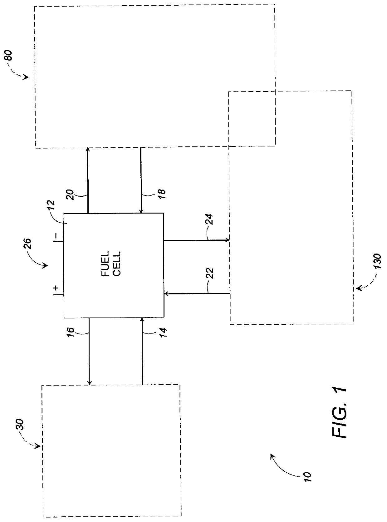
Accordingly, it is an object of the present invention to provide a gas management system for conditioning the reactant streams of a fuel cell, which is compact, lightweight and inexpensive.
A further object of the present invention is to provide a method and apparatus for retaining humidity within the hydrogen fuel stream supplied to the anode inlet of a fuel cell.
Yet another object of the present invention is to provide a method and apparatus for processing deionized cooling water for a fuel cell, which method and apparatus minimizes the quantity of deionized water necessary, and minimizes the overall weight, surface area and aerodynamic drag of the cooling system.

Problems solved by technology

This type of humidification system has been found inefficient for automotive applications, mainly because of the large surface areas required to transfer the necessary quantity of moisture to the gas streams, and because of the undesirable weight of such large-scale systems.
In addition, large quantities of heat energy are consumed in vaporizing moisture in this type of humidification system, which energy consumption reduces system efficiency.
The system of Richman suffers similar disadvantages to that of Dankese; namely, the requirement of large surface areas for effecting moisture transfer and the resulting weight of system components, as well as the consumption of considerable energy in vaporizing the moisture.
This requirement of anode humidification adds additional components to the fuel cell's gas management system, resulting in undesirable increased weight and expense.
Moreover, known humidification systems such as membrane humidifiers or systems utilizing airflow through beds of wetted spheres consume considerable energy in vaporizing water to provide the required humidification.
Therefore, it has been found that known methods of anode humidification are unsuited to automotive applications.
Because stainless steel is a poor thermal conductor, and is heavy and expensive, use of a stainless radiator to effect water-to-air heat transfer has been found to be undesirable, especially in automotive applications.

Method used


Image

  • Fuel cell gas management system
  • Fuel cell gas management system
  • Fuel cell gas management system

Examples


Embodiment Construction

Referring now in detail to the drawing figures wherein like reference numerals represent like parts throughout, FIG. 1 shows the fuel cell gas management system 10 of the present invention, according to a preferred form. The gas management system 10 generally comprises a cathode humidification system 30, an anode humidity retention system 80, and a cooling water processing system 130, all connected to a fuel cell 12. The fuel cell 12 generally comprises a cathode inlet 14, a cathode exhaust 16, an anode inlet 18, an anode exhaust 20, a cooling water inlet 22 and a cooling water discharge 24. Electricity generated by the fuel cell 12 is conducted to a load (unshown) by conductors 26. The fuel cell 12 can be used to supply electrical power for a variety of applications. For example, the fuel cell 12 can be used to recharge the batteries of an electric automobile, or can be used as a power source for commercial or household electrical service.

The fuel cell 12 operates according to know...


PUM


Abstract

A fuel cell gas management system including a cathode humidification system for transferring latent and sensible heat from an exhaust stream to the cathode inlet stream of the fuel cell; an anode humidity retention system for maintaining the total enthalpy of the anode stream exiting the fuel cell equal to the total enthalpy of the anode inlet stream; and a cooling water management system having segregated deionized water and cooling water loops interconnected by means of a brazed plate heat exchanger.

Description

1. Field of the InventionThe present invention relates generally to a method and apparatus for the management and control of various flow streams related to the operation of a fuel cell. The present invention relates more specifically to a fuel cell gas management system which includes subsystems for conditioning the temperature and humidity of the air or other oxidant supplied to a fuel cell's cathode, for anode fuel humidity retention, and for cooling water circulation.2. Description of Related ArtFuel cells generate electrical energy by chemical reaction without altering the electrodes or electrolyte of the cell itself The utility of fuel cells has been known since at least as early as 1939, when Grove demonstrated that electrolysis of water could be reversed using platinum electrodes. Further developments in the fuel cell field have included the development of proton exchange membrane (PEM) fuel cells, phosphoric acid fuel cells, alkaline fuel cells, and fuel cells incorporating...

Claims


Application Information

Patent Timeline
IPC IPC(8): H01M8/04H01M8/10
CPCH01M8/04014H01M8/04029H01M8/04119H01M8/04097H01M8/04223H01M8/1016Y02E60/50H01M8/0267H01M8/043
Inventor DUBOSE, RONALD ARTHUR
Owner EMPRISE TECH ASSOC
Why Eureka
Try Eureka