
Cooling Device for Turbine Nozzle Guide Vane by Liquid Metal With Low Melting Point

Active Publication Date: 2022-07-21
BEIHANG UNIV
View PDF3 Cites 0 Cited by
  • Summary
  • Abstract
  • Description
  • Claims
  • Application Information

AI Technical Summary

Benefits of technology

The present patent proposes a cooling device for a turbine nozzle guide vane that improves heat efficiency and doing work capacity of the engine, enhances cooling effect and prolongs the service life of the guide vane. This is achieved through a closed loop cooling system using a liquid low-melting-point metal or an alloy thereof as the flowing working media which circulates in the cooling channels of the guide vane, taking away a large amount of heat through an efficient heat exchange process. This is different from traditional air film cooling which uses air from a gas compressor. The cooling effect is much better, the guide vane strength is improved, and the whole process is cyclic and environmentally friendly.

Problems solved by technology

Especially, the efficiency of the engine is directly affected by the increase of the turbine inlet temperature.
However, the working conditions of the turbine nozzle are very severe, a first-stage turbine nozzle is connected to the outlet of a combustion chamber, the guide vane is surrounded by gas flow and exposed to high and non-uniform temperature, therefore, the guide vane is easy to burn.
However, all of the introduced cooling air is led out from an air compressor, so that the opportunity of doing work is lost in order to meet the cooling requirement, and the heat efficiency and the doing work capacity of the engine are greatly reduced.
Furthermore, under the condition that the cooling air does not participate in a thermodynamic cycle, heat is absorbed from the main combustion gas flow in the thermal protection process of high-temperature parts, so that heat loss in the main combustion gas flow is aggravated; unstable flow of gas flow is easily caused after the cooling air is mixed with the main flow, so that aerodynamic loss of the main combustion gas flow is increased.

Method used


Image

  • Cooling Device for Turbine Nozzle Guide Vane by Liquid Metal With Low Melting Point
  • Cooling Device for Turbine Nozzle Guide Vane by Liquid Metal With Low Melting Point
  • Cooling Device for Turbine Nozzle Guide Vane by Liquid Metal With Low Melting Point

Examples


Embodiment Construction

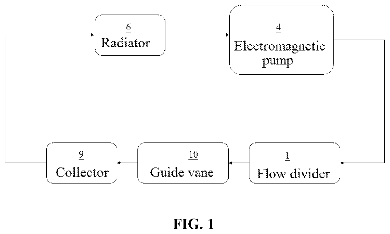
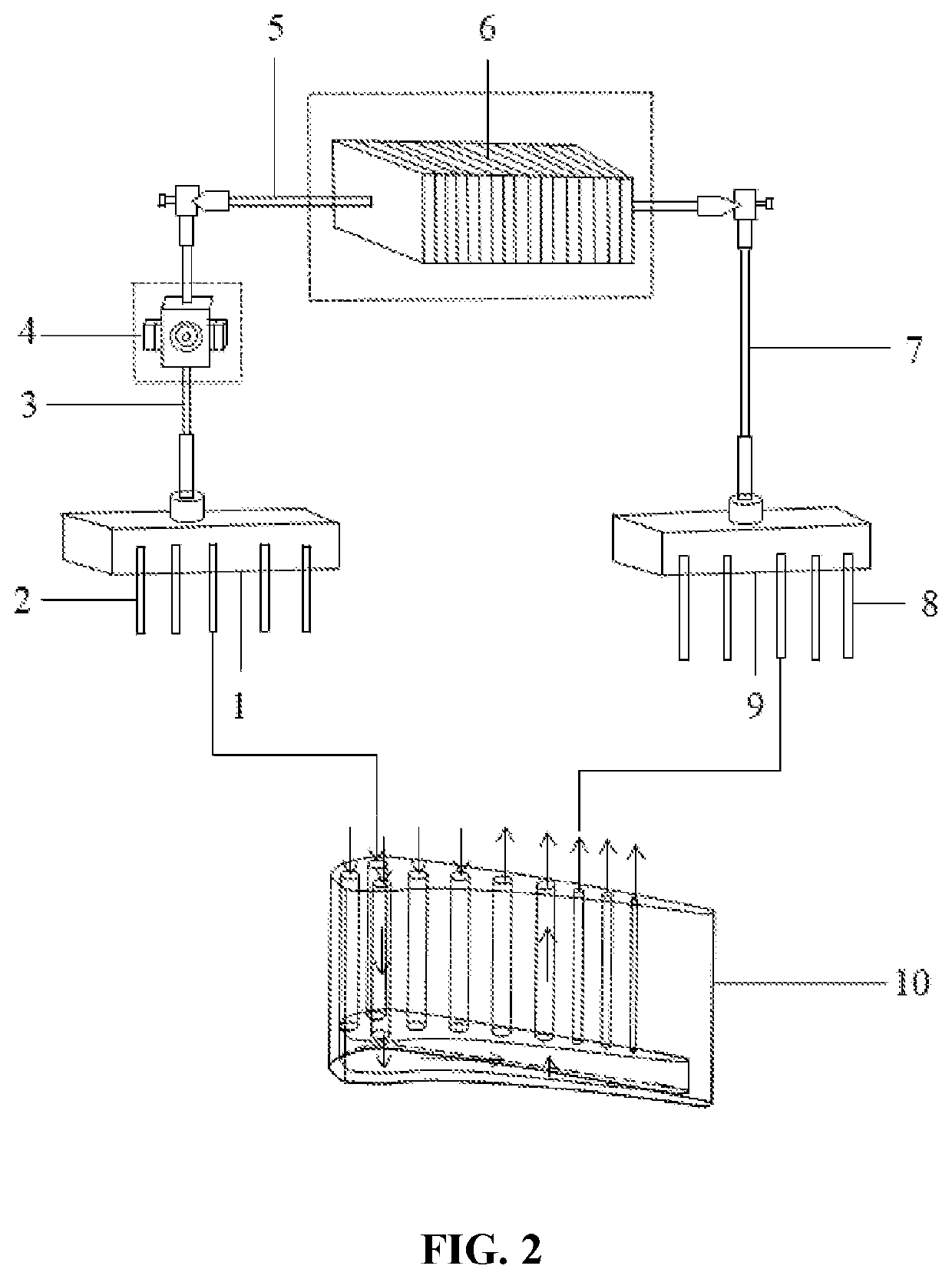
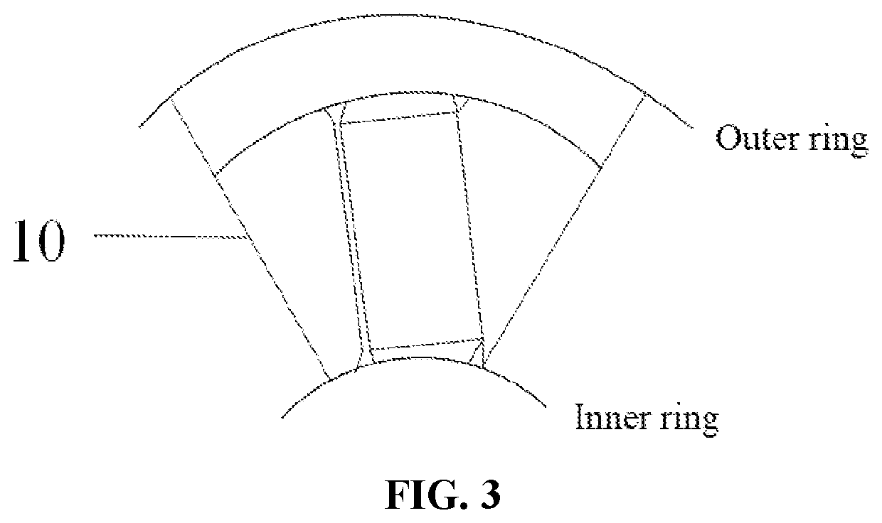
[0030]FIG. 1 is a schematic logic control diagram of a cooling device for a turbine nozzle guide vane with a low-melting-point metal as a flowing working media according to one embodiment of this disclosure. FIG. 2 is a schematic structural diagram of the cooling device for a turbine nozzle guide vane with the low-melting-point metal at an outer portion of an outer ring of a guide vane as the flowing working media. FIG. 3 is a schematic structural diagram of the guide vane. FIG. 4 is a schematic perspective view of the guide vane.

[0031]As shown in FIG. 4, in the embodiment, a plurality of cooling channels are arranged in the guide vane 10. A cavity 13 is provided at a bottom inside the guide vane 10. Each cooling channel communicates with the cavity 13. Some of the plurality of cooling channels are inflow guide vane cooling channels 11, and the rest of the plurality of cooling channels are outflow guide vane cooling channels 12. As shown in FIG. 1, referring to FIG. 2 to FIG. 4, the...


PUM


Abstract

Disclosed is a cooling device for a turbine nozzle guide vane with a low-melting-point metal as a flowing working media. A plurality of cooling channels and a cavity are arranged in a guide vane. The cooling device includes a flow divider, a collector, a radiator and an electromagnetic pump, the cooling device and the guide vane form a closed loop. Liquid low-melting-point metal or alloy thereof as the flowing working medium is driven by the electromagnetic pump to circularly flow in the closed loop and dissipate rapidly through the radiator. Air cooling is not adopted in the present disclosure, cooling air originally led out from a gas compressor is saved so as to increase the propelling power of an aircraft. Air film holes do not need to be formed in the outer surface of the guide vane so as to improve strength of the guide vane.

Description

CROSS REFERENCE TO RELATED APPLICATION[0001]This patent application claims the benefit and priority of Chinese Patent Application 202110082035.4 filed on Jan. 21, 2021, the disclosure of which is incorporated by reference herein in its entirety as part of the present application.TECHNICAL FIELD[0002]The present disclosure relates to a cooling device for a turbine nozzle guide vane of an aviation gas turbine engine, in particular to a cooling device for a turbine nozzle guide vane with a low-melting-point metal or an alloy of the low-melting-point metals as a flowing working media.BACKGROUND ART[0003]Aviation gas turbine engines need to achieve design goals by increasing total pressure ratio and turbine inlet temperature in order to improve thrust-to-weight ratio and thermal efficiency. Especially, the efficiency of the engine is directly affected by the increase of the turbine inlet temperature. At present, the turbine inlet temperature reaches up to 1800-2050 K, and under such high...

Claims


Application Information

Patent Timeline
IPC IPC(8): F01D5/18F01D9/04
CPCF01D5/181F01D9/041F05D2240/128F05D2260/232F05D2260/205F05D2260/213F05D2260/22141F05D2240/126F01D25/12F01D9/02F05D2260/208F01D9/065
Inventor LUO, XIANGZHANG, ZHEWU, ZEYU
Owner BEIHANG UNIV
Learn More