
Plate heat exchanger

A technology of heat exchanger and flat plate, applied in the field of flat heat exchanger and its assembly, to achieve the effect of optimizing pressure loss and optimizing heat exchange efficiency

Active Publication Date: 2008-04-16
MODINE MFG CO
View PDF2 Cites 25 Cited by
  • Summary
  • Abstract
  • Description
  • Claims
  • Application Information

AI Technical Summary

Problems solved by technology

However, this structure has the disadvantage that the fluid in the central region of the heat exchanger is predominantly laminar

Method used


Image

  • Plate heat exchanger
  • Plate heat exchanger
  • Plate heat exchanger

Examples


Embodiment Construction

[0020] Before describing embodiments of the invention in detail, it is to be understood that, in its application, the invention is not limited to the details of construction and arrangement of parts set forth in the following description or shown in the drawings. The invention is capable of other embodiments and of being practiced or carried out in various ways. Also, it is to be understood that the phraseology and terminology employed herein are for the purpose of description and should not be regarded as limiting. The use of "comprising", "comprising" or "having" and variations thereof herein is meant to encompass the items listed thereafter and equivalents thereof as well as additional items. Unless otherwise indicated or limited, the terms "mount", "connect", "support" and "couple" and variations thereof are used broadly and include both direct and indirect mounting, connecting, supporting and coupling. Furthermore, "connected" and "coupled" are not limited to physical or...


PUM


Abstract

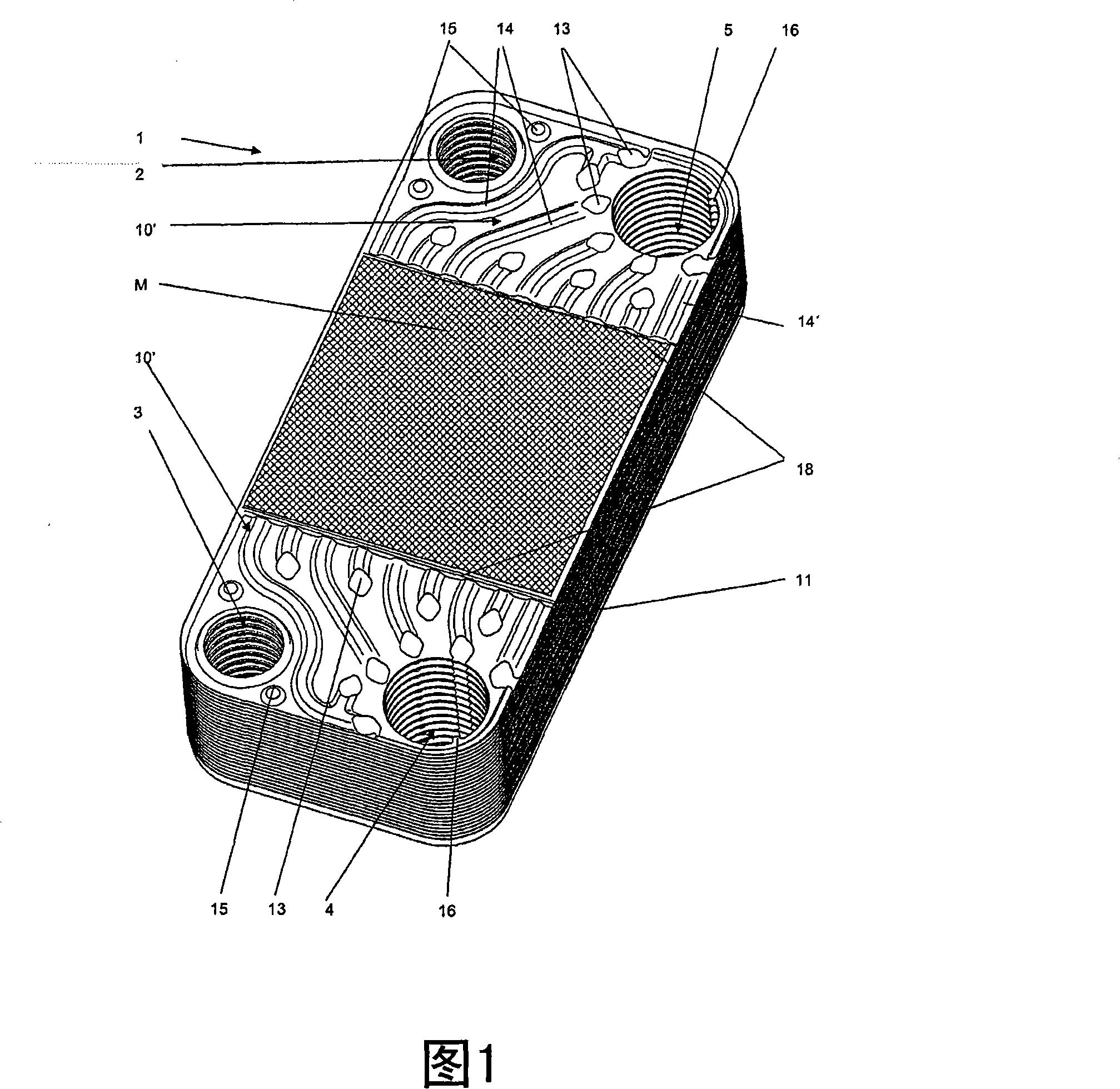
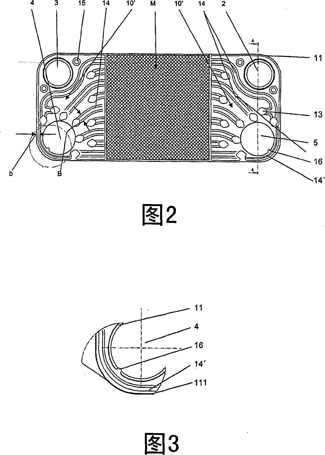
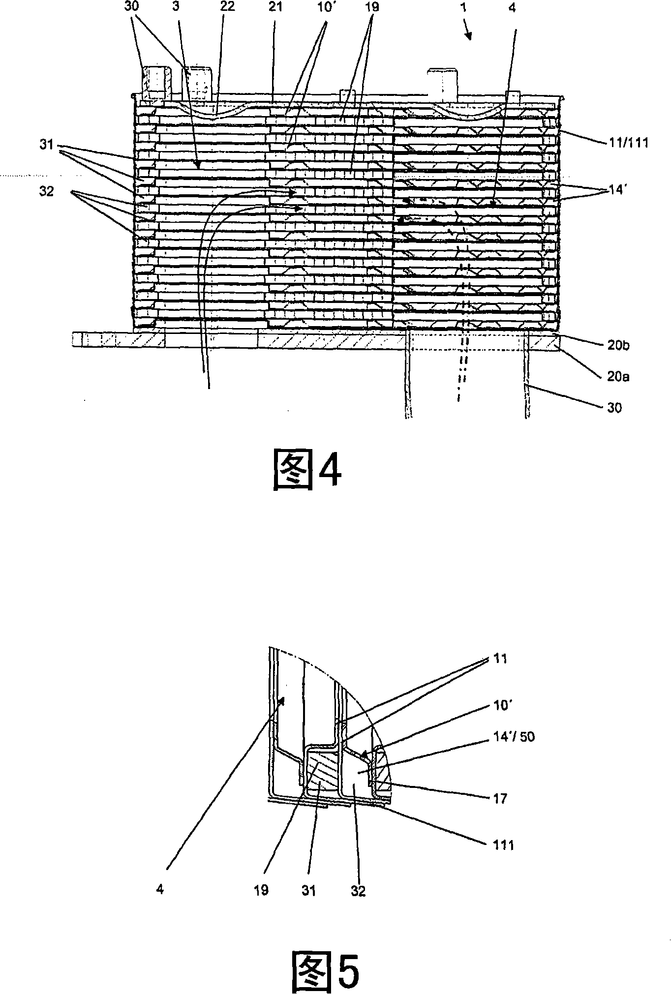
The invention relates to a flat heat exchanger comprising a plurality of trough-shaped heat exchanger plates stacked on top of each other, the heat exchanger plates having edges abutting against each other. The plates may have flow conduits for the cooling fluid and for another fluid between the heat exchanger plates. The flow ducts are assembled with inserts in the form of turbulator plates. The heat exchanger has at least four inlet and outlet openings in the corners of the heat exchanger plates forming two vertical ducts for the cooling fluid and two for the other fluid in the stack. a vertical conduit. An insert in a flow conduit for a cooling fluid consists of one or more components. The flow duct for the cooling fluid is equipped with a plate-like insert with a width guiding the duct in the region near the opening. The insert is formed as a turbulence generator in the central area between the plate-like parts. The openings are arranged in the corners in such a way that only a narrow strip is left occupied by the guiding duct whose width is significantly smaller than that of the other guiding ducts.

Description

[0001] Related Application Cross Reference [0002] This application claims priority from German Patent Application No. DE 10 2006048 305.7 filed on October 12, 2006, the entire content of which is hereby incorporated by reference. technical field [0003] The present invention relates to a flat plate heat exchanger and a method of assembling the same. Background technique [0004] German Patent No. DE 197 09 601 A1 discloses a conventional plate heat exchanger. In its flow ducts, the flat plate heat exchanger has turbulent plates (ie lamellae) which are divided into segments in order to reduce pressure losses. The segments generally consist of turbulence plates of the same type, each segment rotated by 90° relative to the adjacent segment. They match each other in shape so as not to create gaps. However, it is clear that the overall pressure loss is undesirably high and internal pressure stability needs to be improved. [0005] EP 1 152 204 B1 discloses a flat plate he...

Claims


Application Information

Patent Timeline
IPC IPC(8): F28D9/00F28F9/24
CPCF28F3/10F28F3/046F28F13/12F28D9/005F28F3/044F28F3/025Y10S165/916
Inventor 安德烈亚斯·克普克里恩哈德·韦尔曼
Owner MODINE MFG CO
Learn More