Porous separator and lithium secondary battery comprising same

a separator and lithium secondary technology, applied in the field of porous separator and lithium secondary batteries, can solve the problems of insufficient discharge capacity at low temperatures, difficulty in manufacturing, and low capacity of the battery, so as to reduce the cost, reduce the weight, and increase the reliability of the dendrite short

Pending Publication Date: 2022-02-17
LG ENERGY SOLUTION LTD
View PDF7 Cites 0 Cited by
  • Summary
  • Abstract
  • Description
  • Claims
  • Application Information

AI Technical Summary

Benefits of technology

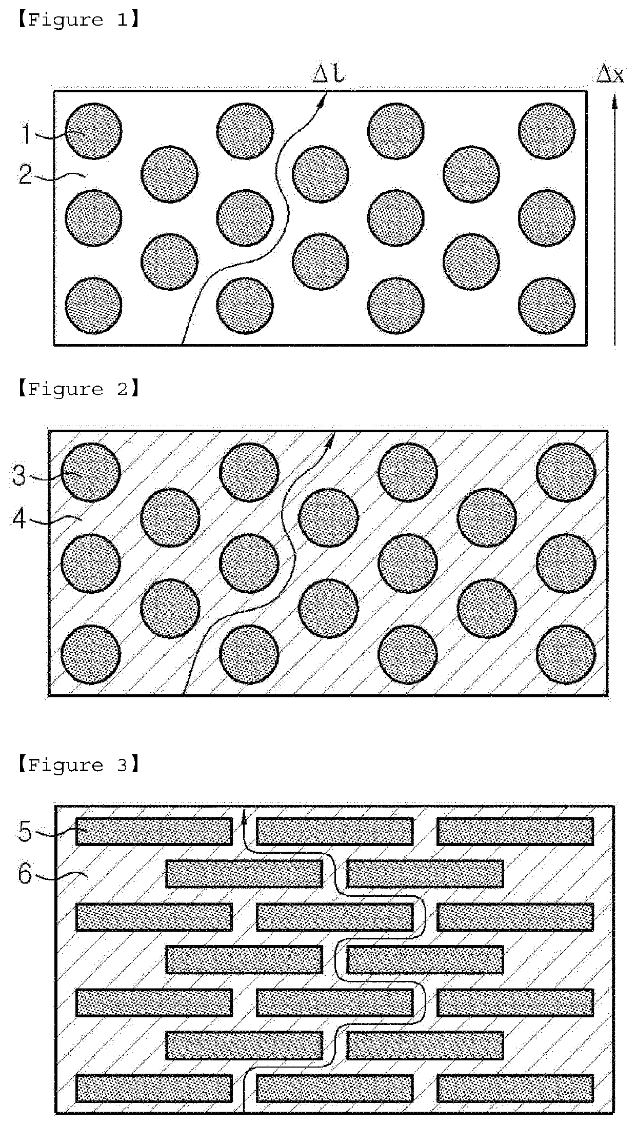
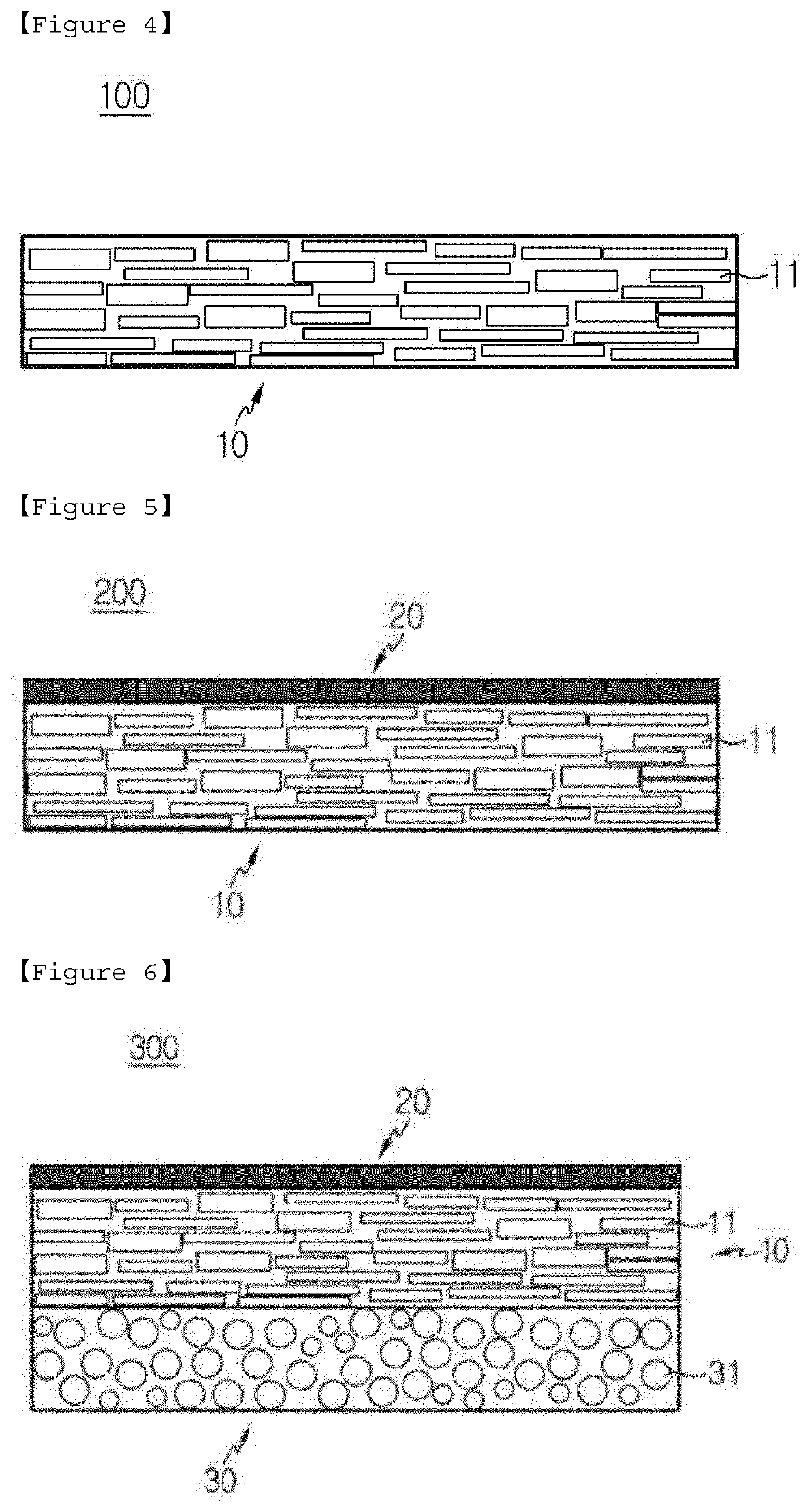
The present invention provides a battery with a porous separator that reduces the cost and weight of the battery while improving its safety. The separator prevents the growth of lithium dendrites and improves the battery's output characteristics by coating a ceramic with a high dielectric constant on the positive electrode contacts. The separator's porous layer contains plate-type inorganic particles that increase the tortuosity, making it difficult for dendrites to reach the positive electrode from the negative electrode. The lack of a porous polymer base material also reduces the risk of heat shrinkage when exposed to high temperatures.

Problems solved by technology

However, the lithium ion battery has safety problems such as ignition and explosion due to the use of an organic electrolyte solution, and has a disadvantage of being difficult to manufacture.
The recent lithium ion polymer battery is regarded as one of the next generation battery by improving the weaknesses of this lithium ion battery, but the capacity of the battery is still relatively low compared to the lithium ion battery, and in particular, the discharge capacity at low temperatures is insufficient, and improvements for this are urgently required.
In the safety characteristics of an electrochemical device, if the electrochemical device is overheated and thus shows thermal runaway, or the separator is penetrated, there is a high risk of causing an explosion.
In particular, a polyolefin-based porous substrate, which is commonly used as a separator for the electrochemical device, exhibited extreme heat shrinkage behavior at the temperature of 100° C. or more due to the property of the material and the property of the preparation process including stretching, thereby causing the short circuit between the positive electrode and negative electrode.
However, in this case, the porous layer may have coating defects on the surface due to cracks occurring during the manufacturing process, for example, a drying process.
Thus, the organic / inorganic composite porous layer can be easily detached from the polyolefin-based porous substrate when the secondary battery is assembled or when the battery is used, which leads to deterioration of the safety of the battery.
Also, in order to form the porous layer, the slurry for forming the porous layer applied to the polyolefin-based porous substrate has a problem in that the degree of compaction of the particles is increased during drying, thereby resulting in densely packed parts and thus lowering air permeability.
In addition, there is a problem that the heavy metal components inevitably mixed in the manufacturing process of the electrode plate of the battery and the preparation process of the raw materials are deposited on the surface of the negative electrode as they are redoxed during the activation of the battery, and as a result, acicular crystals (dendrites) of metal lithium cause micro-short on the positive electrode or the negative electrode, thereby causing a voltage drop of the battery.

Method used


Image

  • Porous separator and lithium secondary battery comprising same
  • Porous separator and lithium secondary battery comprising same

Examples


example 1

[0094]

[0095]After mixing PVdF-HFP polymer binder (LBG Grade from Arkema company) and inorganic particles (alumina, NW-710 Grade from T-cera company, aspect ratio=67) in a ratio of 2:8, the mixture was mixed with a solvent of N-methyl-2-pyrrolidone (NMP) at a solid concentration of 40% to prepare a coating solution.

[0096]The prepared coating solution was coated with an applicator on a polyethylene terephthalate (PET) film (SKC company, RX12G 50 μm) surface-treated by a corona of 0.7 Kw intensity, and then dried in a Mathis oven at 130° C. for 5 minutes to prepare a PET film coated with a porous separator having a thickness of 100 μm.

[0097]The PET film coated with the porous separator was rolled on a roll press machine (Calendering machine, CIS company CLP-2025H) to form a porous separator having a thickness of 20 μm and then peeled off the PET film.

[0098]Thereafter, an aluminum metal layer of 0.5 μm was formed on one surface of the porous separator under the conditions of 10 mTorr va...

example 2

[0104]A coating solution was prepared by mixing PVdF-HFP polymer binder (LBG Grade from Arkema company) with BaSrTiO3 in a ratio of 1:9 and then mixing the mixture with a solvent of N-methyl-2-pyrrolidone (NMP) at a solid concentration of 20 wt. %. A lithium secondary battery was prepared in the same manner as in Example 1, except that the coating solution is coated on the other surface of the porous separator prepared in Example 1, in which no metal layer is formed, in the same manner as in Example 1 to prepare a porous separator.

experimental example 1

me Characteristics of Battery

[0108]Using a Small Cell cycler device from PNE SOLUTION company, the charging was performed by CC charging at a constant current (CC) of 0.2 C until it becomes 4.25V, and then charging once with a current cut-off of 5% relative to 1 C at a constant voltage (CV) of 4.25V, and thereafter, the discharging was performed at a constant current of 0.5 C until it becomes 3V, which constitute 1 cycle. This cycle was performed repeatedly.

[0109]The cycle performance according to the cycle characteristics and 2 C discharging capacity relative to 0.2 C were measured. The results are shown in Table 1 below.

TABLE 12C dischargingCycle performancecapacity relative to(capacity retention0.2C (%)under 90%)Example 191%38 cycleExample 296%46 cycleComparative91%30 cycleExample 1Comparative91%20 cycleExample 2Comparative91%27 cycleExample 3

[0110]Referring to Table 1, it was found that the results of applying the porous inorganic separators of Comparative Examples 1 to 3 show t...


PUM

PropertyMeasurementUnit
aspect ratioaaaaaaaaaa
thicknessaaaaaaaaaa

Abstract

The present invention relates to a porous separator comprising a porous layer containing a plurality of plate-type inorganic particles and a first binder polymer positioned on part or all of the surface of the plate-type inorganic particles to connect and fix between the plate-type inorganic particles; and a metal layer formed on any one surface of the porous layer, and a lithium secondary battery comprising the same.

Description

TECHNICAL FIELD[0001]The present application claims the benefit of priority based on Korean Patent Application No. 10-2018-0122101 filed on Oct. 12, 2018, all the contents of which is incorporated herein by reference.[0002]The present invention relates to a porous separator and a lithium secondary battery including the same, which can block lithium ion dendrites and has improved high temperature safety by excellent thermal properties.BACKGROUND ART[0003]Recently, there is increasing interest in energy storage technology. As the application area thereof extends to the energy for mobile phones, camcorders, notebook PCs, and even electric vehicles, the effort of research and development of electrochemical devices is being carried out more and more concretely. Electrochemical devices are the most noteworthy area in this respect, and among them, the development of a secondary battery capable of charging / discharging is the focus of attention. Recently, in developing these batteries, resea...

Claims


Application Information

Patent Timeline
Patent Type & Authority Applications(United States)
IPC IPC(8): H01M50/457H01M50/446H01M50/434H01M50/443H01M10/052H01M50/489H01M4/38H01M4/40H01M50/491
CPCH01M50/457H01M50/446H01M50/434H01M50/443H01M2004/027H01M50/489H01M4/382H01M4/405H01M10/052H01M50/449H01M50/491H01M50/431H01M10/0525Y02E60/10H01M10/4235H01M50/463H01M50/46
Inventor CHOI, WOONGCHULCHOI, JUNGHUNKANG, YONGHEEJANG, MINCHULYOUN, SUK ILSON, BYOUNGKUK
Owner LG ENERGY SOLUTION LTD
Why Eureka
Try Eureka