
Heat Treatment Process and System for Increased Pitch Yields

a heat treatment process and yield technology, applied in the field of carbon based pitch production improvement, can solve the problems of increasing the exposure of countries to these materials, and achieve the effects of increasing the total pitch yield, and reducing the risk of qi level

Active Publication Date: 2021-01-28
KOPPERS DELAWARE INC
View PDF0 Cites 2 Cited by
  • Summary
  • Abstract
  • Description
  • Claims
  • Application Information

AI Technical Summary

Benefits of technology

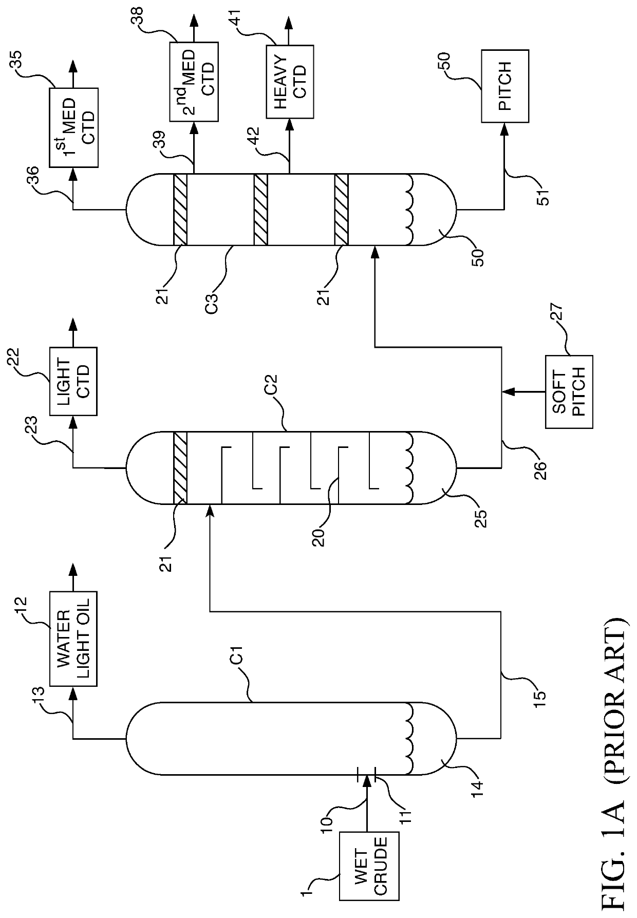
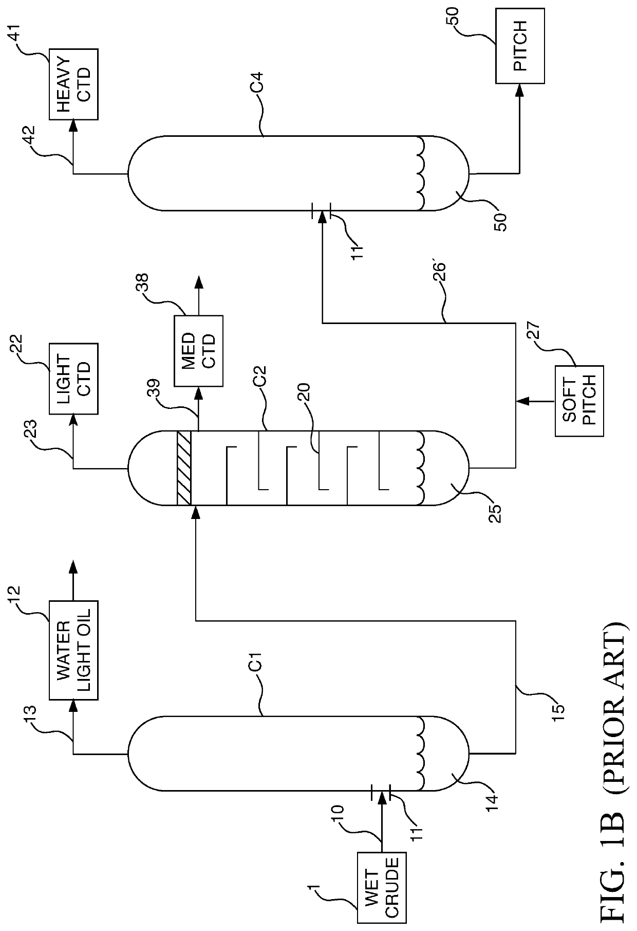
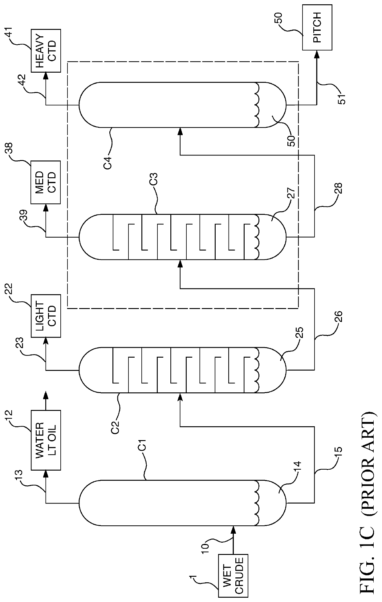
The present invention provides heat treatment processes that improve the efficiency of pitch production and increase yields from less economical byproducts. The processes utilize heavy distillate and decant oil from petroleum production as starting materials and subject them to heat treatment at specific temperatures, pressures, and residence times to recover additional pitch and increase total pitch yields. Control of related temperature, pressure, and residence variables in the heat treatment process is critical to retain minimal QI levels and avoid mesophase formation. The invention also attempts to achieve turbulent heating of the feed material followed by a plug flow through the reactor section of the heat treatment devices with the goal of maintaining a continuous and consistent flow of starting material for roughly equivalent exposure to the heat. The heat-treated starting materials may then routed back into the pitch production process as added feedstock to increase yields. The invention also discusses the potential increase in the softening point of commercial pitch due to the removal of potentially carcinogenic compounds, and provides a way to utilize this additional heavy distillate withdrawn during pitch formation to generate further pitch.

Problems solved by technology

Many of these compounds may be carcinogenic and some states and countries are becoming increasingly sensitive to exposure to these materials by people and the environment.

Method used


Image

  • Heat Treatment Process and System for Increased Pitch Yields
  • Heat Treatment Process and System for Increased Pitch Yields
  • Heat Treatment Process and System for Increased Pitch Yields

Examples


example 1

Determining Rate of Heavy Distillate Removal

[0101]Certain experiments were performed to determine a maximum flow rate at which heavy distillate 141 may be removed from the third column C3 of the first embodiment of coal tar pitch production system 100 discussed above without impairing the overall performance of the pitch production system 100. Heavy distillate 141 heat treatment is important for the separation of B(a)P as well as to maintain a higher softening points in the resulting pitch 150, such as about 130° C. Mettler.

[0102]Given a goal of increasing pitch yield by 5%, the flow rate required for heat treatment system 300 was calculated as follows. Assuming annual tar throughput is about 300,000 MT / year, 5% of this figure is about 15,000 MT / year, which would be additional pitch required. This rate of 15,000 MT / year divided by an estimated yield of 30% is about 50,000 MT / year, divided by 300 days / year in operation provides 166 MT / day or 7 MT / h for flow rate through the heat trea...

example 2

Determining Reactor Temperatures

[0109]To further design full-scale application of the heat treatment systems 300, some base cases were evaluated, specifically the process heater 314 temperature. Here, temperatures of 420, 445, 471, 497 and 522° C. were evaluated. The lower limit for this evaluation was based on preliminary autoclave results which showed limited reactivity. The upper limit was based on the autoignition temperature of heavy distillate, which have been measured to 542° C. For safety reasons the final reactor temperature has limited to 522° C.

[0110]Previous experiments have shown that heavy distillate can be subjected to temperatures of 550° C. for 5.2 min without forming mesophase or coke. In addition, previous experiments on long retention times provided the following data, shown in Table 10.

TABLE 10TemperatureRetention timeYield %(° C.)(hr)(softening point 115° C.)395415.7401210.6420526.7

[0111]Based on these previous data, kinetic-based simulations were determined in...

example 3

Testing Various Temperatures and Retention Times Coal Tar

[0113]Test runs were performed to assess the feasibility of heat treating heavy distillate to convert it to pitch. These initial experiments were performed at various temperatures between 365 and 510° C. and retention times ranging from 4.5 minutes to 2 hours. A reaction constant was derived from these results. Two additional experiments were performed adiabatically to measure whether the reaction is endothermic, thoroughly insulating the reactor to ensure that the measured temperature of the reactor was not due to the temperature of the oven, but instead of the heavy distillate inside. The experiments were performed using a plug flow reactor.

[0114]Experiments were all performed in the same general manner. Heavy distillate was placed in a feed tank and pumped through the reactor by a rotational pump. The reactor is housed in an oven with a pre-heater, and different sized reactors were also used ranging from 299-330 mL in size....


PUM

PropertyMeasurementUnit
pressureaaaaaaaaaa
temperatureaaaaaaaaaa

Abstract

Pitch production systems utilizing coal tar or decant oil for coal. or petroleum based pitch are disclosed. Total pitch production yields are increased by heat treating distillate fractions from the pitch production process. A heat treatment system and process are disclosed in embodiments. The heaviest distillates having the highest molecular weights are subjected to heat treatment, though other embodiments contemplate heat treating a variety of combined distillate fractions. The heat treatment systems require heat soaking the distillate(s) at elevated temperatures of 459-535° C. at a near-constant temperature with near-uniform flow. A fraction of the heat-treated distillate may be reintroduced to the pitch production system as part of a continuous process.

Description

BACKGROUND OF THE INVENTIONField of the Invention[0001]This invention relates to improvements in the production of carbon based pitches. More particularly, the invention relates to heat treatment of distillation byproducts from the processing of coal tar and petroleum to optimize pitch yields while minimizing quinoline insoluble content and creation of mesophase in pitch.Description of the Prior Art[0002]Coal is a vital starting material in producing a number of beneficial products the modernized world has come to depend upon. Most notably, bituminous coal mined from the ground may be heated in an oven called a “coke battery” through destructive distillation or carbonization of the coal to produce coke and coal tar. Coke is widely used as a fuel and as a reagent source in the production of steel. Coal tar, the dark liquid removed from the coal in the coking process, is useful as a component in sealcoat used in sealing roads, asphalt, roofs, treated wood and other construction materi...

Claims


Application Information

Patent Timeline
Patent Type & Authority Applications(United States)
IPC IPC(8): C10C1/16B01D3/14B01D3/06
CPCC10C1/16B01D3/06B01D3/143C10C1/19C10C3/002C10C3/06
Inventor MALMQVIST, MICHAEL BECHCAIRNS, BILLY JAYMUELLER, CARL CAMILLEBARON, JOHN THOMASDIETZ, JAMES T.
Owner KOPPERS DELAWARE INC
Learn More