
A process of manufacturing of segments for carbon thrust bearing

a technology of carbon thrust bearing and manufacturing process, which is applied in the direction of rotary bearings, engine components, metal-working apparatus, etc., can solve the problems of high processing cost, increased labor intensity, and increased maintenance costs of conventional manufacturing processes, so as to reduce the amount of handling effort, reduce maintenance, and cost-effective

Active Publication Date: 2020-12-17
SARADVA ATULKUMAR RAGHAVJIBHAI
View PDF0 Cites 0 Cited by
  • Summary
  • Abstract
  • Description
  • Claims
  • Application Information

AI Technical Summary

Benefits of technology

The present invention provides a process for manufacturing segments for carbon thrust bearing that results in high strength, hardness, toughness, ductility, and uniform grain structure. This process also reduces the time and cost of manufacturing and reduces the possibility of defects in the segments.

Problems solved by technology

This conventional manufacturing process consumes more time from wax injection process to gates grinding process and requires skilled labors for preparing the molten metal as per the required grade and for spectrographic testing of said molten metal.
Further, processing steps of conventional manufacturing process are expensive as it requires more infrastructures, costly machineries, consumables and energy which ultimately results in high-cost of the finished segments for carbon thrust bearings.
Further, the quenching stress of the bearing parts reduces the strength of the bearing and bearing parts.
Further, the physical and mechanical properties i.e. strength, hardness, ductility, toughness and uniform grain structure of the segments produced by conventional manufacturing process are poor.

Method used


Image

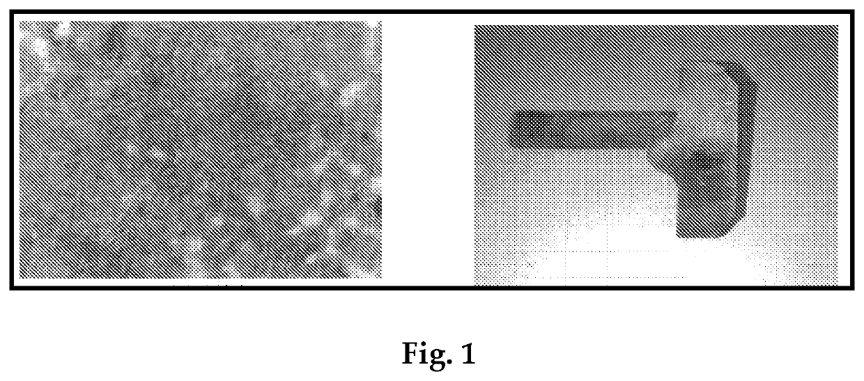
  • A process of manufacturing of segments for carbon thrust bearing
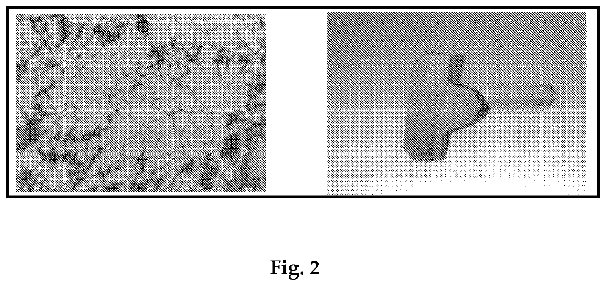
  • A process of manufacturing of segments for carbon thrust bearing
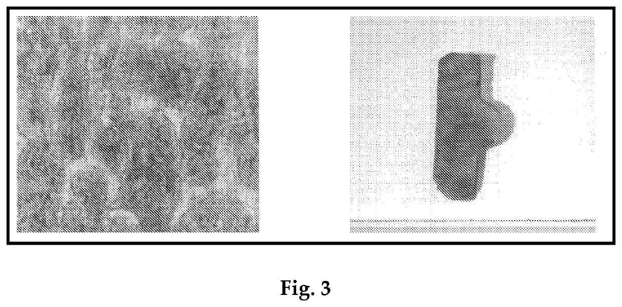
  • A process of manufacturing of segments for carbon thrust bearing

Examples


example 1

[0028]a) The stainless steel round bar of grade AISI 420B (SS 420B) was selected as feed stock or raw materials and was undergone cutting operation in cutting press to form billets;

[0029]b) Said billets were undergone heating process at temperature of 900° C.-1000° C. in induction furnace;

[0030]c) The steel billets obtained in step (b) were undergone hot forging process in mechanical press using closed forging dies for forming segments of desired shape;

[0031]d) The segments obtained in step (c) were undergone stress relieving process at temperature of 545° C.-555° C. to reduce internal residual stress and to prevent the formation of excessive thermal stresses;

[0032]e) The segments obtained in step (d) were undergone hardening process at temperature of 1040° C. to increase the hardness and toughness and to acquire uniform grain structure of the segment;

[0033]f) The segments obtained in step (e) were subjected to tempering process at temperature of 245° C.-255° C. to reduce brittlenes...


PUM

PropertyMeasurementUnit
Temperatureaaaaaaaaaa

Abstract

A process of manufacturing of segment for carbon thrust bearing uses stainless-steel (SS) round bars / sheets / logs of suitable grade as raw material. The SS round bars / sheets / logs undergo cutting operation to cut into SS billets. The billets successively undergo heating and hot forging processes to form segments of desired shapes. Thereafter, the segment is subjected to heat treatment process i.e. stress relieving, hardening and tempering process successively for obtaining consistent and uniform grain structure, mechanical properties and physical properties of segments which are cost-effective in terms of lower maintenance and lower handling efforts. After heat-treatment process, segment undergoes surface-finishing processes i.e. grinding, lapping and polishing successively for obtaining mirror like surface finishing that gives greater anti-friction property and lower co-efficient of friction. The manufacturing process according to present invention yields consistent grain structure, refine, dense and uniform microstructure of segments which imparts optimum strength, ductility, toughness and resistance to impact and fatigue.

Description

FIELD OF INVENTION[0001]The present invention relates to a process of manufacturing of segments for carbon thrust bearing and more particularly it relates to a manufacturing process which reduces the time for producing the segments from raw materials and improves the mechanical and physical properties i.e. strength, hardness, ductility, toughness and uniform grain structure of the segments for carbon thrust bearing.BACKGROUND OF INVENTION[0002]The carbon thrust bearings play critical role in submersible motors, pumps, and other mechanical devices as an alternative to regular bearings. The carbon thrust bearings are used worldwide in submersible motors, pumps to ensure proper supply of water to the topmost levels of building and to ensure the safety of the motor and pump in dry running condition. The carbon thrust bearing comprises components i.e. thrust plate, carbon pad, segments and segment carrier. In carbon thrust bearing, the segments play vital role for withstanding the fluctu...

Claims


Application Information

Patent Timeline
IPC IPC(8): B21D53/10F16C17/04
CPCF16C17/04B21D53/10F16C2220/46F16C2220/70C21D9/40F16C33/14C21D2261/00F16C2223/10C21D1/18C21D1/30C21D1/26C21D1/42C21D6/002C21D8/0205C22C38/04C22C38/02C22C38/44F16C17/06F16C33/108B21J1/06B21J5/022B21J5/025B21K1/04B24D11/001Y02P10/25C21D1/00C21D1/10C21D1/25C21D6/02B21K1/76C21D9/00F16C33/00
Inventor SARADVA, ATULKUMAR RAGHAVJIBHAI
Owner SARADVA ATULKUMAR RAGHAVJIBHAI
Learn More