
Power module and manufacturing method thereof

a technology of power modules and manufacturing methods, applied in the direction of transformers/inductances, magnetic cores of transformers/inductances, printed circuit non-printed electric components association, etc., can solve the problems of increased power consumption, increased requirements for cooling systems, and increased occupied space and power loss ratios, so as to achieve optimized and integrated connection of magnetic components and power devices, high efficiency, and enhanced flexibility of arrangement of power devices and other electronic devices

Pending Publication Date: 2020-08-13
DELTA ELECTRONICS SHANGHAI CO LTD
View PDF6 Cites 0 Cited by
  • Summary
  • Abstract
  • Description
  • Claims
  • Application Information

AI Technical Summary

Benefits of technology

This patent is about a new power module design that allows for flexible arrangement and optimization of power devices and other electronic components. It has a high efficiency, power density, and heat dissipation capacity. The size of the power module can be reduced, making it more competitive. The design can be customized for different applications, and more functions are integrated into the power module. The use of copper blocks, conductive vias, leading frames, or circuit boards combined with the magnetic component and integrated between the wiring layers simplifies the process of embedding the magnetic component and conductive components within the board, improving production efficiency and reducing manufacturing cost.

Problems solved by technology

Consequently, the ratio of occupied space and power loss are increased.
Furthermore, as the performance of various types of chips continues to increase, its power consumption also increases, and the point power supply is closer to the load, which brings higher requirements for cooling system.
However, compared with the linear power supply, the circuit of the switching power supply is more complicated, and the magnetic components / capacitors are usually utilized as the energy storage / filtering function therein, so that it is not easy to achieve chip level integration.
However, with the advancement of technology, the independent optimization of a single component has gradually reached the limit.
It is impossible to further achieve high efficiency, high power density and high heat dissipation capacity by optimizing a single component individually.

Method used


Image

  • Power module and manufacturing method thereof
  • Power module and manufacturing method thereof
  • Power module and manufacturing method thereof

Examples


first embodiment

[0039]FIG. 2 is a schematic cross-sectional view illustrating a power module according to the present disclosure. The power module 1 includes a first board 10, a magnetic component 20, a second board 30 and at least one power device 60. The first board 10 includes a first side 11, a second side 12, a first conductive component 30 and a second conductive component 40. The first side 11 and the second side 12 are opposite to each other. Preferably but not exclusively, the first side 11 is the highest surface of the first board 10, and the second side 12 is the lowest surface of the first board 10. In the embodiment, both of the first conductive component 30 and the second conductive component 40 are disposed between the first side 11 and the second side 12. The magnetic component 20 is disposed between the first side 11 and the second side 12 of the first board 10 and includes at least one magnetic core 23 and at least one winding 26. Preferably but not exclusively, the top surface 21...

second embodiment

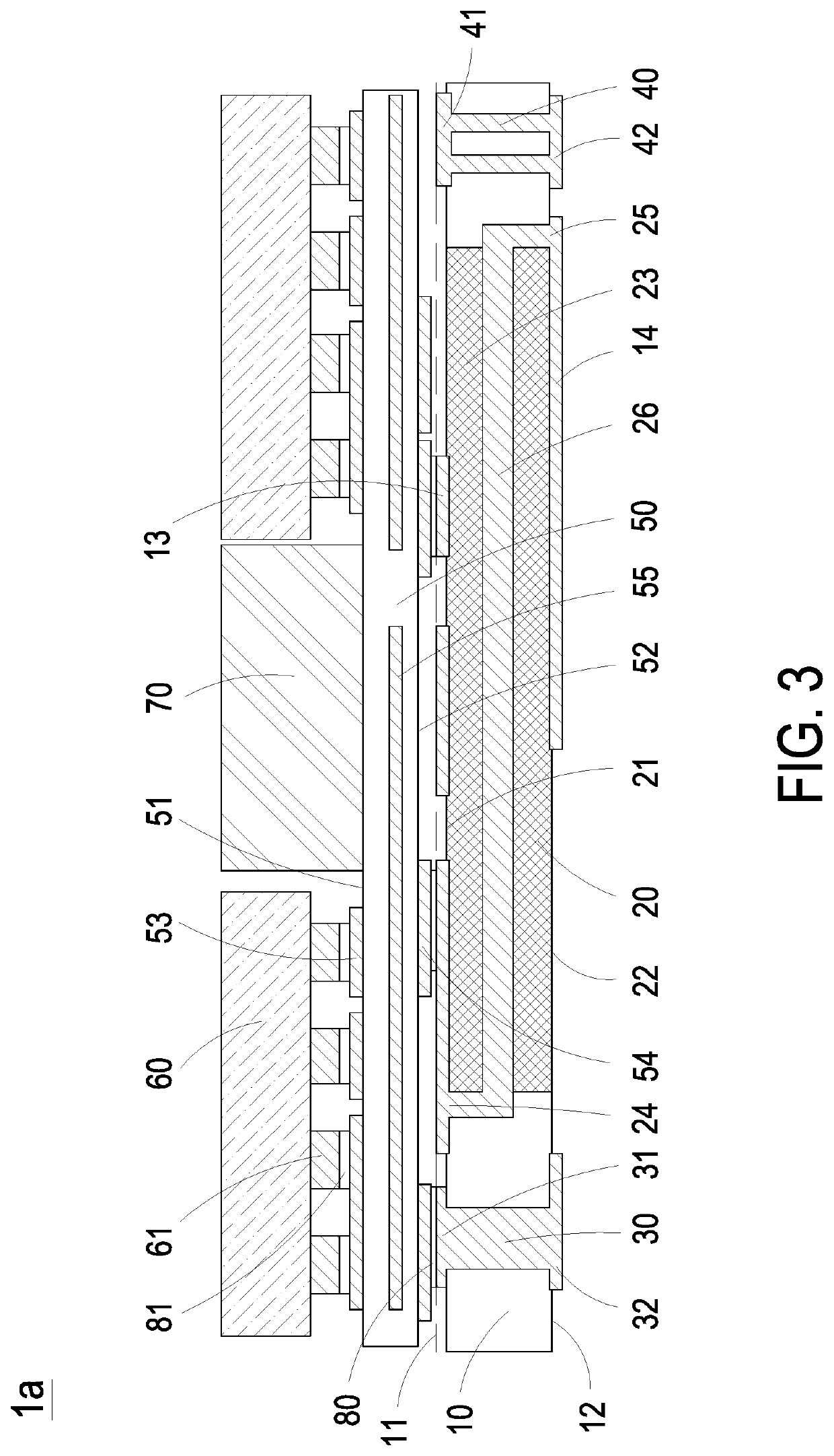
[0042]FIG. 3 is a schematic cross-sectional view illustrating a power module according to the present disclosure. In the embodiment, the structures, elements and functions of the power module 1a are similar to those of the power module 1 in FIG. 2, and are not redundantly described herein. In the embodiment, the power module 1a further includes at least one electronic device 70 disposed on the third wiring layer 53, which is disposed on the third side 51 of the second board 50. The pin of the at least one electronic device 70 is electrically connected to the third wiring layer 53 of the second board 50 through a solder (not shown). Preferably but not exclusively, the at least one electronic device 70 is adjacent to the power device 60, or disposed between two power devices 60. In an embodiment, a heat sink (not shown) is further integrally disposed on the power device 60 and the electronic device 70. However, it is not an essential feature to limit the present disclosure, and not re...

third embodiment

[0043]FIG. 4 is a schematic cross-sectional view illustrating a power module according to the present disclosure. In the embodiment, the structures, elements and functions of the power module 1b are similar to those of the power module 1a in FIG. 3, and are not redundantly described herein. In the embodiment, the power module 1b includes at least one first electronic device 71 and at least one second electronic device 72 disposed on the third wiring layer 53, which are disposed on the third side 51 of the second board 50. The leading pins of the first electronic device 71 and the second electronic device 72 are electrically connected to the third wiring layer 53 of the second board 50 through a solder (not shown), respectively. The first electronic device 71 is disposed between the two power devices 60. The second electronic device 72 is disposed nearby a margin region of the third side 51 of the second board 50. In the embodiment, the first electronic device 71 and the second elect...


PUM


Abstract

A power module and a manufacturing method thereof are disclosed. The power module includes a first board, a magnetic component, a second board and a power device. The first board includes a conductive component disposed between a first side and a second side opposite to each other. The magnetic component is disposed between the first side and the second side and includes a magnetic core and a winding. A first conductive terminal and a second conductive terminal are led out on the first side and the second side, respectively. The second board is disposed on the first board and includes a third side and a fourth side opposite to each other. The fourth side faces the first side. The power device is disposed on the third side of the second board and electrically connected to the first board.

Description

CROSS-REFERENCE TO RELATED APPLICATION[0001]This application claims priority to China Patent Application No. 201910402768.4, filed on May 15, 2019. This application is a continuation-in-part application of U.S. application Ser. No. 16 / 130,850 filed on Sep. 13, 2018 and entitled “POWER MODULE AND MANUFACTURING METHOD THEREOF”, which is a continuation-in-part of U.S. application Ser. No. 15 / 158,016 filed on May 18, 2016 and entitled “MAGNETIC ASSEMBLY”. The entire contents of the above-mentioned patent applications are incorporated herein by reference for all purposes.FIELD OF THE INVENTION[0002]The present disclosure relates to a power module, and more particularly to an optimized power module and a manufacturing method thereof.BACKGROUND OF THE INVENTION[0003]With the increasing requests of human intelligent life, the increasing requirements of developing intelligent products, and the growing of Internet of Things (IoT), the requirements of data transmission and processing are incre...

Claims


Application Information

Patent Timeline
IPC IPC(8): H05K1/18H01F27/29H05K3/36H05K3/32H01F27/24H05K3/46H05K3/24H05K1/14
CPCH01F27/24H05K3/36H05K3/24H05K3/32H05K1/14H05K2201/1003H05K1/181H01F27/292H05K3/4644H01F17/04H01F17/0013H05K1/188H05K1/144H05K3/34H05K1/165H05K2201/086H05K2201/10166H05K1/0263H05K3/4046H05K1/186H01F41/076H05K1/185
Inventor HONG, SHOUYUZHOU, JINPINGZHOU, MINXIN, XIAONIJI, PENGKAILU, KAILIANG, LEZHAO, ZHENQING
Owner DELTA ELECTRONICS SHANGHAI CO LTD
Learn More